Author Archive

Generating Electricity from Urea Using NiCoMo/Graphene Catalysts

Electro-oxidizing urea in water has the dual benefit of generating electricity and treating wastewater. In alkaline media, the sluggish kinetics of the urea oxidation reaction, CO(NH2)2 + 6OH → N2↑ + CO2↑ + 5H2O + 6e, due to its transfer of six electrons demand efficient catalysts to speed up this process.

A research team led by Xiujuan Sun and Rui Ding, both at Xiangtan University, China, used a co-precipitation method to synthesize urea-oxidation catalysts. These catalysts comprised of graphene-anchored nanoparticles of metallic Ni, Co, and Mo, as well as their alloys and hydro/oxides (NCM/G) (Figure 1). NCM/G with the optimal composition displayed a mass activity of 140.9 mA cm-2 mgcat-1 and an onset potential of 1.32 V vs. RHE (current density = 10 mA/cm2). Their results are published in Chemical Communications (DOI: 10.1039/D0CC02132F).
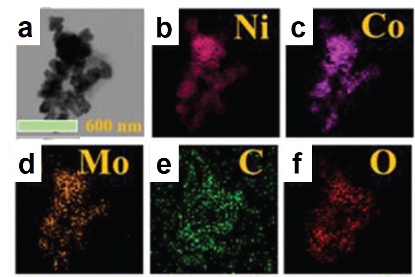
Figure 1. Representative (a) transmission electron microscopy image and (b-f) elemental mappings of the synthesized catalyst.

The catalysts exhibited different catalytic activities dependent on their chemical compositions, which were tunable by varying the moles of the Ni, Co, and Mo precursors. Cyclic voltammograms of various NCM/G all showed markedly increased current density at potentials beyond 0.3 V vs. Ag/AgCl in urea-containing aqueous solutions (Figure 2a), marking their catalytic activity for urea oxidation. Among all the tested catalysts, NCM/G with Ni:Co:Mo = 80:10:10 achieved the largest current density at 0.6 V vs. Ag/AgCl, indicating its highest catalytic activity. Additionally, chronoamperometry demonstrated that increasing the Mo content was beneficial for maintaining catalyst stability, as the current density of NCM/G with the lowest amount of Mo (the black curve in Figure 2b) decayed the fastest. Combining the results of cyclic voltammetry and chronoamperometry, the authors deduced that the optimal molar ratio of Ni:Co:Mo was 80:10:10.

Figure 2. (a) Cyclic voltammograms (scan rate: 1 mV/s) and (b) chronoamperometry (potential: 0.5 V vs. Ag/AgCl) profiles of NCM/G with different Ni, Co, and Mo contents. Electrolyte: 1.0 M KOH + 0.33 M urea in water. The molar ratios of Ni:Co:Mo of NCM/G 90505, 811, and 71515 are 90:5:5. 80:10:10, and 70:15:15, respectively.

The optimization of the chemical composition demonstrated in this work can rationalize the development of high-performance, metallic electrocatalysts for urea oxidation.

For expanded understanding, please read:

Trimetallic NiCoMo/Graphene Multifunctional Electrocatalysts with Moderate Structural/Electronic Effects for Highly Efficient Alkaline Urea Oxidation Reaction

Wei Shi, Xiujuan Sun, Rui Ding, Danfeng Ying, Yongfa Huang, Yuxi Huang, Caini Tan, Ziyang Jia, and Enhui Liu

Chem. Commun., 2020, DOI: 10.1039/D0CC02132F


Tianyu Liu acknowledges Zacary Croft at Virginia Tech, U.S., for his careful proofreading of this post.


About the blogger:

Tianyu Liu obtained his Ph.D. (2017) in Chemistry from the University of California, Santa Cruz, in the United States. He is passionate about the communication of scientific endeavors to both the general public and other scientists with diverse research expertise to introduce cutting-edge research to broad audiences. He is a blog writer for Chem. Comm. and Chem. Sci. More information about him can be found at http://liutianyuresearch.weebly.com/.

Digg This
Reddit This
Stumble Now!
Share on Facebook
Bookmark this on Delicious
Share on LinkedIn
Bookmark this on Technorati
Post on Twitter
Google Buzz (aka. Google Reader)

Potassium-Ion Batteries Welcome A New Electrode from Iron Compounds

A research team led by Jiang Zhou and Shuquan Liang of Central South University, China, recently identified iron oxyhydroxide (β-FeOOH) as a K-ion battery electrode material. It is reportedly the first iron-oxide-based compound to serve in K-ion batteries. The results have been published in Chemical Communications (DOI: 10.1039/d0cc01009j).

K-ion batteries are a new type of rechargeable battery emerging after Li-ion batteries, the charge-storage functionality of which is associated with the intercalation and de-intercalation of K+. Due to the relative abundance of K+ to Li+, K-ion batteries are poised as a promising alternative to Li-ion batteries.

The researchers made the electrode by a hydrothermal reaction. Specifically, they dispersed Super P® (SP), an electrically conductive additive, into FeCl3 aqueous solutions. The mixture was then heated at 150 °C for 10 h. The resultant powder (FeOOH-SP), comprised of uniformly mixed, crystalline β-FeOOH nanorods and Super P particles (Fig. 1), was directly used as an electrode material.

Figure 1. Transmission electron microscopy images of (a, b) FeOOH-SP and (c) FeOOH. (d) Elemental mappings of C, Fe, and O in FeOOH-SP.

The authors investigated the electrochemical properties of FeOOH-SP in K-ion batteries. At a current density of 100 mA/g, FeOOH-SP exhibited a stable specific capacity of ~200 mAh/g, approximately double and quadruple that of SP and FeOOH alone, respectively (Fig. 2a). The specific capacity of FeOOH-SP was maintained at ~100 mAh/g when the current density increased to 2000 mA/g (Fig. 2b), showing its fast-charging capability. Additionally, the authors observed that the crystalline β-FeOOH nanorods amorphized upon K+ intercalation after being discharged (Fig. 2c). Their crystallinity was only partially restored when being re-charged (Fig. 2d). The loss of crystallinity, however, did not undermine the charge-storage capacity of FeOOH-SP.

Figure 2. (a) Specific capacities of FeOOH-SP, SP, and FeOOH at different charge-discharge cycles. Current density: 100 mA/g. (b) Rate capability of FeOOH-SP. (c, d) Transmission electron microscopy images of (c) discharged and (d) charged FeOOH-SP. Red dashed boxes highlight crystalline regions. The electrolyte was a mixture of ethylene carbonate and diethyl carbonate containing 1 M potassium bis(fluorosulfonyl)imide.

Considering the low-cost of iron oxyhydroxide, FeOOH-SP could reduce the manufacturing cost of K-ion batteries and increase the affordability of electrochemical charge storage devices.


For expanded understanding, please read:

β-FeOOH: A New Anode for Potassium-Ion Batteries

Xiaodong Shi, Liping Qin, Guofu Xu, Shan Guo, Shuci Ma, Yunxiang Zhao, Jiang Zhou, and Shuquan Liang

Chem. Commun., 2020, 56, 3713-3716.

Tianyu Liu acknowledges Zacary Croft at Virginia Tech, U.S., for his careful proofreading of this post.

About the blogger:

Tianyu Liu obtained his Ph.D. (2017) in Chemistry from the University of California, Santa Cruz, in the United States. He is passionate about the communication of scientific endeavors to both the general public and other scientists with diverse research expertise to introduce cutting-edge research to broad audiences. He is a blog writer for Chem. Comm. and Chem. Sci. More information about him can be found at http://liutianyuresearch.weebly.com/.

Digg This
Reddit This
Stumble Now!
Share on Facebook
Bookmark this on Delicious
Share on LinkedIn
Bookmark this on Technorati
Post on Twitter
Google Buzz (aka. Google Reader)

Upgrading Methanol Using Zinc-Indium-Sulfide and Solar Light

Based on the chemical formulae, can you figure out how to convert methanol (CH3OH) into ethylene glycol (HOCH2CH2OH)? If you have constantly practiced your organic chemistry, you might have already found the answer: combining two methanol molecules and eliminating one hydrogen molecule (H2). Indeed, this methanol-coupling reaction is a promising, low-cost chemical route to upgrade methanol to chemicals with more carbon atoms. The feasibility of this route, however, is low under mild conditions without catalysts to drive the reaction.

A group of scientists led by Shunji Xie and Ye Wang, both at Xiamen University, China, has developed an environmentally friendly catalyst, Zn2In2S5, for room-temperature methanol coupling to produce ethylene glycol using solar light. This work has been published in Chemical Communications (DOI: 10.1039/c9cc09205f).

The synthesized Zn2In2S5 catalyst is comprised of 1-3 layers of nanosheets. Through a hydrothermal reaction, the researchers first synthesized multi-layer Zn2In2S5 stacks in an aqueous solution (Fig. 1a). Subsequent ultrasonication exfoliated the stacks into few-layer Zn2In2S5­ nanosheets that were confirmed by transmission electron microscopy (Fig. 1b). Zn2In2S5 is a semiconductor and its valence band (VB) resides below the redox potential of ethylene glycol/methanol (Fig. 1c). The band alignment enables Zn2In2S5 to catalyze the oxidation of methanol to ethylene glycol.

Figure 1. (a) A scheme of the synthesis procedures of few-layer ZnmIn2Sm+3 (m=1-3) nanosheets. (b) Transmission electron microscopy images of few-layer Zn2In2S5 nanosheets. (c) Positions of the valence bands (VBs) and conduction bands (CBs) of different metal-sulfide semiconductors.

Zn2In2S5 and its composite exhibited high catalytic activity. Upon irradiation with visible light and solar light (AM 1.5), photo-induced electrons and holes generated in Zn2In2S5 (Fig. 2a). The electrons reduced protons in electrolytes and liberated hydrogen gas, while the holes moved to the Zn2In2S5 surface and split the C—H bond of methanol, forming ·CH2OH radicals. These radicals then dimerized into ethylene glycol. Through depositing a hydrogen evolution co-catalyst, cobalt monophosphide (CoP), and illuminating using AM 1.5 solar light, the authors observed that the CoP/Zn2In2S5 catalyst achieved a rapid formation rate (18.9 mmol gcat-1 h-1) and high selectivity (~90%) of ethylene glycol (Fig. 2b). The yield of ethylene glycol after 12 h of reaction was 4.5%.

Figure 2. (a) A scheme of the formation mechanisms of ethylene (from methanol) and 2,3-butanediol (from ethanol) on Zn2In2S5. EG: ethylene glycol. 2,3-BD: 2,3-butanediol. (b) Formation rates and ethylene glycol selectivity of Zn2In2S5 and CoP/Zn2In2S5 under two illumination conditions. AM 1.5: air mass 1.5 solar irradiance. HCHO is a byproduct.

Zn2In2S5 was demonstrated to effectively catalyze C—H cleavages and C—C couplings of different alcohols, e.g., from ethanol to 2,3-butanediol.


To find out more, please read:

C–H Activations of Methanol and Ethanol and C–C Couplings into Diols by Zinc–Indium–Sulfide Under Visible Light

Haikun Zhang, Shunji Xie, Jinyuan Hu, Xuejiao Wu, Qinghong Zhang, Jun Cheng, and Ye Wang

Chem. Commun., 2020, DOI: 10.1039/c9cc09205f


The blogger acknowledges Zac Croft at Virginia Tech, U.S., for his careful proofreading of this post.


About the blogger:

Tianyu Liu obtained his Ph.D. (2017) in Chemistry from the University of California, Santa Cruz, in the United States. He is passionate about the communication of scientific endeavors to both the general public and other scientists with diverse research expertise to introduce cutting-edge research to broad audiences. He is a blog writer for Chem. Comm. and Chem. Sci. More information about him can be found at http://liutianyuresearch.weebly.com/.

Digg This
Reddit This
Stumble Now!
Share on Facebook
Bookmark this on Delicious
Share on LinkedIn
Bookmark this on Technorati
Post on Twitter
Google Buzz (aka. Google Reader)

What Does the New Carbon Allotrope Look Like, Theoretically?

A long-lasting dispute regarding the most stable structure of cyclo[18]carbon, a new carbon allotrope, has been settled. Cyclo[18]carbon is an all-carbon ring comprised of eighteen interconnected carbon atoms. It is proposed to have two possible structures: the cumulenic structure with only carbon-carbon double bonds (Figure 1a), and the polyynic structure having alternating carbon-carbon triple and single bonds (Figure 1b). Recent experiments have confirmed that the polyynic structure is the stable form, but theorists were still puzzled: Why can’t the various computational methods reach an agreement on the molecular structure of cyclo[18]carbon?

Figure 1. The (a) cumulenic and (b) polyynic structures of cyclo[18]carbon.

Anton J. Stasyuk and coworkers from the University of Girona, Spain, offered an answer in ChemComm (DOI: 10.1039/C9CC08399E). They found that the simulated structure strongly depended on the type of functionals used in density functional theory (DFT), which is a computational tool to derive energy-minimum molecular structures. The functionals used for DFT calculations are mathematical terms that can tune the simulation accuracy.

The authors discovered that the weight of the exact exchange term (HF% exchange) in the DFT functionals determined the most stable simulated structure of cyclo[18]carbon. The researchers compared 13 functionals with various percentages of HF% exchanges. They found that functionals with the HF% exchange higher than 50% predicted the appreciably different lengths of the neighboring bonds (quantified as the bond length alternation, the vertical axis of Figure 2), corresponding to the polyynic structure (Figure 2, red zone). This structure was recently observed experimentally. Functionals with lower HF% exchange either obtained the cumulenic structure (Figure 2, green zone) or the mixed cumulenic-polyynic structure (Figure 2, gray zone).

Figure 2. Variation in the HF% exchange of the B3LYP functional changed the predicted molecular structure of cyclo[18]carbon. BLA: Bond length alternation.

With the correct functionals identified, the authors revealed the electronic properties of cyclo[18]carbon. Calculations showed that cyclo[18]carbon was a strong electron acceptor, making it the smallest all-carbon electron acceptor reported so far.


To find out more, please read:

Cyclo[18]Carbon: Smallest All-Carbon Electron Acceptor

Anton J. Stasyuk, Olga A. Stasyuk, Miquel Solà, and Alexander Voityuk

Chem. Commun., 2019, DOI: 10.1039/C9CC08399E

Tianyu Liu acknowledges Zac Croft at Virginia Tech, U.S., for his careful proofreading of this post.


About the blogger:

Tianyu Liu obtained his Ph.D. (2017) in Chemistry from the University of California, Santa Cruz, in the United States. He is passionate about the communication of scientific endeavors to both the general public and other scientists with diverse research expertise to introduce cutting-edge research to broad audiences. He is a blog writer for Chem. Comm. and Chem. Sci. More information about him can be found at http://liutianyuresearch.weebly.com/.

Digg This
Reddit This
Stumble Now!
Share on Facebook
Bookmark this on Delicious
Share on LinkedIn
Bookmark this on Technorati
Post on Twitter
Google Buzz (aka. Google Reader)

How does LiNO3 Make Lithium–Sulfur Batteries Long-Lasting?

Lithium–sulfur (Li–S) batteries are rechargeable batteries with elemental sulfur and metallic lithium as the cathode and anode, respectively. These batteries are promising electrochemical energy storage devices because their energy densities are three to five times higher than those of Li-ion batteries. Unfortunately, the practicality of Li–S batteries is hindered by their short lifetimes due to two processes that occur on the Li anode surface: the growth of Li dendrites and the irreversible polysulfide reduction. Adding LiNO3 into battery electrolytes has proven to be useful to prolong battery lifetimes, but the underlying mechanism is uncertain.

In Chemical Communications (doi: 10.1039/c9cc06504k), Sawangphruk and coworkers from Vidyasirimedhi Institute of Science and Technology, Thailand have offered valuable insights to settle the dispute over the effects of LiNO3. The researchers performed theoretical reactive molecular dynamics simulations and elucidated two roles of LiNO3 in Li–S batteries.

The first discovery was that LiNO3 promoted the formation of smooth, double-layered solid electrolyte interfaces (SEIs) on the Li surface. SEIs are thin layers composed of electrolyte-decomposition products, including Li-containing organic compounds and inorganic salts. By simulating the charge distribution near a Li metal surface, the authors mapped the Li-Li radial pair distribution profiles in three phases (Fig. 1a). The similarity between the profiles of the dense phase (the Li metal) and the nest phase evidenced the presence of an amorphous, Li-containing layer atop the Li metal surface. Beyond this amorphous layer was a liquid-like film with Li element distributed homogenously. This double-layered SEI altered the kinetics of Li deposition onto the Li surface upon charging, resulting in smooth and dense SEIs (Figs. 1b and c) that avoided Li dendrite formation.

Figure 1. (a) Li-Li radial pair distribution functions of the dense phase (Li metal), nest phase (the layer atop Li), and disperse phase (the outermost layer). (b and c) Top-view scanning electron microscopy images of the Li metal surface in (b) LiNO3-free and (c) LiNO3-containing electrolytes. Both electrolytes had lithium bis(trifluoromethanesulfonyl)imide (LiTFSI) as a solute, and 1,3-dioxolane (DOL) and 1,2-dimethoxyethane (DME) as solvents.

Another effect of LiNO3 was to capture polysulfide compounds. Through their simulations, the authors deduced the reaction pathways involving the electrolyte molecules, LiNO3 or LiClO4 additives, and lithium polysulfide compounds (Fig. 2a). The concentration of LixNOy, the reduction products of LiNO3 when contacted Li metal, in the LiNO3-containing electrolyte was much higher than those in the additive-free and LiClO4-containing electrolytes. First-principle calculations proved that the highly electro-negative N and O atoms in LixNOy could capture lithium polysulfides via dipole-dipole interactions. This process reduced the likelihood of polysulfide reduction on Li that passivated anodes.

Figure 2. (a) A scheme of the reaction pathways involving the electrolyte, additive, and polysulfide molecules. (b) Product distributions in electrolytes without additives and with LiNO3 or LiClO4.

LiNO3 elongates the lifetimes of Li–S batteries by forming smooth SEIs to impede Li dendrite formation, while maintaining the reactivity of Li anodes by capturing lithium polysulfides.


To find out more, please read:

Insight into the Effect of Additives Widely Used in Lithium–Sulfur Batteries

Salatan Duangdangchote, Atiweena Krittayavathananon, Nutthaphon Phattharasupakun, Nattanon Joraleechanchai, and Montree Sawangphruk

Chem. Commun., 2019, 55, 13951-13954

Tianyu Liu acknowledges John Elliott of Virginia Tech, the U.S., for his careful proofreading of this post.

About the blogger:

Tianyu Liu obtained his Ph.D. (2017) in Chemistry from the University of California, Santa Cruz, in the United States. He is passionate about the communication of scientific endeavors to both the general public and other scientists with diverse research expertise to introduce cutting-edge research to broad audiences. He is a blog writer for Chem. Commun. and Chem. Sci. More information about him can be found at http://liutianyuresearch.weebly.com/.

Digg This
Reddit This
Stumble Now!
Share on Facebook
Bookmark this on Delicious
Share on LinkedIn
Bookmark this on Technorati
Post on Twitter
Google Buzz (aka. Google Reader)

Strengthening Li+-Coordination Decelerates Li-Dendrite Growth in Li-Metal Batteries

Lithium-metal batteries are a family of rechargeable batteries with higher charge-storage capacities than those of lithium-ion batteries. The boosted charge-storage performance of lithium-metal batteries is rooted in its anode material – Li metal, as it possesses an ultrahigh theoretical capacity (3860 mAh/g). However, the growth of dendrites on Li surfaces during charging could short-circuit batteries, cause combustion, and trigger explosions.

A research group led by Feng Li at the Institute of Metal Research, Chinese Academy of Sciences, recently devised a strategy to suppress the notorious Li dendrite growth in lithium-metal batteries. By tuning the composition of the electrolytes, the authors strengthened the coordination between Li+ and electrolyte solvents, which slowed the growth of Li dendrites. This work has been published in Chemical Communications (doi: 10.1039/C9CC07092C).

The researchers introduced an electrolyte additive, tetraethylene glycol dimethyl ether (TEGDME), as a coordination ligand to Li+. Compared to other components in the electrolyte, i.e., 1,2-dimethoxyethane (DME) and 1,3-dioxolane (DOL), TEGDME contains more oxygen atoms that can form multiple, robust coordination bonds with Li+. Specifically, density functional theory calculations showed that the binding energy between Li+ and electrolyte molecules increased by 0.31 eV after introducing TEGDME, reaching an absolute value of 4.93 eV. The enhanced binding force made the separation of Li+ from TEGDME (a prerequisite for Li-dendrite growth) energetically consuming and kinetically sluggish (Figure 1). These characteristics could decelerate Li-dendrite formation and elongate battery lifetimes.

Figure 1. Lithium-dendrite growth in different electrolytes: (a) weak coordination with Li+ promotes fast dendrite growth while (b) strong coordination with Li+ decelerates dendrite formation.

To confirm the above idea, the authors assembled lithium batteries with TEGDME+DME+DOL or DME+DOL electrolytes. Cycling stability tests demonstrated that the battery with the TEGDME-added electrolyte survived 60 charge-discharge cycles at a current density of 1C, whereas the capacity of the battery without TEGDME rapidly decayed beyond 30 cycles under identical testing conditions (Figure 2a). Scanning electron microscopy images revealed that the number of rod-shaped Li dendrites on the anode in the TEGDME-added electrolyte (Figure 2c) was less than that in the TEGDME-free electrolyte (Figure 2b), further confirming that the enhanced cycling stability resulted from the Li-dendrite suppressing effect of TEGDME.

Figure 2. (a) Cycling stability performance of lithium-metal batteries with two different electrolytes. The cathode material in both batteries was lithium iron phosphate (LFP). (b and c) SEM images of the Li anode surface after charging in (b) DME+DOL and (c) DME+DOL+TEGDME electrolytes.

This work highlights the importance of tailoring the electrolyte composition for preserving the stability and safety of lithium-metal batteries.


To find out more, please read:

Suppressing Lithium Dendrite Formation by Slowing Its Desolvation Kinetics

Huicong Yang, Lichang Yin, Huifa Shi, Kuang He, Hui-Ming Cheng, and Feng Li

Chem. Commun., 2019, doi: 10.1039/C9CC07092C

Tianyu Liu acknowledges Xiaozhou Yang of Virginia Tech, the U.S., for his careful proofreading of this post.

About the blogger:

Tianyu Liu obtained his Ph.D. (2017) in Chemistry from the University of California, Santa Cruz, in the United States. He is passionate about the communication of scientific endeavors to both the general public and other scientists with diverse research expertise as a way to introduce cutting-edge research to broad audiences. He is a blog writer for Chem. Commun. and Chem. Sci. More information about him can be found at http://liutianyuresearch.weebly.com/.

Digg This
Reddit This
Stumble Now!
Share on Facebook
Bookmark this on Delicious
Share on LinkedIn
Bookmark this on Technorati
Post on Twitter
Google Buzz (aka. Google Reader)

Synthesizing Polymers Using CO2

Ring-opening polymerizations produce commercial polymeric materials including epoxy resins, but they usually liberate small molecules such as the greenhouse gas, CO2. In the context of climate change, it is urgent to reduce CO2 emissions. Recently, a group of UK researchers led by Prof. Charlotte K. Williams at the University of Oxford developed a step-growth polymerization method that self-consumed CO2. The work has been published in a recent issue of Chemical Communications.

The synthesis involved two catalytic cycles (Figure 1). The first cycle polymerized L-lactide-O-carboxyanhydride into poly(L-lactide acid) (PLLA) via a ring-opening polymerization and released one CO2 molecule per polymer repeat unit. In the second cycle, epoxide molecules (cyclohexeneoxide) combined with the CO2 generated in the first step and grew into poly(cyclohexene carbonate) (PCHC) from the terminal ends of the PLLA chains. A di-zinc-alkoxide compound catalyzed both cycles and coupled the two processes together. The product is PLLA-b-PCHC block copolymers, which are composed of PLLA and PCHC covalently tethered together.

Figure 1. The two catalytic cycles are joined by a zinc-based catalyst, [LZn2(OAc)2]. The CO2 gas produced in the first step serves as a reactant in the second step. OCA: O-carboxyanhydride; ROP: ring-opening polymerization; CHO: cyclohexeneoxide; ROCOP: ring-opening copolymerization.

The two reactions resulted in block copolymers with few byproducts. In-situ 1H NMR revealed that the reactants in the first step (LLAOCA) were rapidly consumed during the first four hours (Step I, Figure 2a), and the concentration of PLLA increased notably. The concentration of PCHC only markedly increased after the concentration of PLLA saturated (Step II, Figure 2a). The byproduct of the second step, trans-cyclohexene carbonate, exhibited consistently low concentrations. The pronounced single peak in each size-exclusion chromatogram of the corresponding product confirmed the presence of block copolymers, instead of polymer mixtures (Figure 2b). Although the authors did not fully elucidate the origin of the excellent selectivity towards the block copolymer, they speculated that the change in CO2 partial pressure played a role. Significantly, nearly all CO2 molecules were consumed in the second step, with 91% incorporated into the block copolymer, and 9% converted to the byproduct.

Figure 2. (a) The evolution of the concentrations of PLLA, PCHC, and trans-CHC (the byproduct of the second step) with reaction time. (b) Size-exclusion chromatograms of the products at different reaction times. Mn: number-average molecular weight; Đ: polydispersity.

The authors are investigating the detailed polymerization mechanism, as well as identifying new catalysts to expand the polymerization scheme to other polymers.


To find out more, please read:

Waste Not, Want Not: CO2 (Re)cycling into Block Copolymers

Sumesh K. Raman, Robert Raja, Polly L. Arnold, Matthew G. Davidson, and Charlotte K. Williams

Chem. Commun., 2019, 55, 7315-7318


About the blogger:

Tianyu Liu obtained his Ph.D. (2017) in Chemistry from University of California, Santa Cruz in the United States. He is passionate about scientific communication to introduce cutting-edge research to both the general public and scientists with diverse research expertise. He is a blog writer for Chem. Commun. and Chem. Sci. More information about him can be found at http://liutianyuresearch.weebly.com/.

Digg This
Reddit This
Stumble Now!
Share on Facebook
Bookmark this on Delicious
Share on LinkedIn
Bookmark this on Technorati
Post on Twitter
Google Buzz (aka. Google Reader)

1+1>2: Bridging Constituents in Hetero-Structured Hydrogen Evolution Photocatalysts

Solar-driven water reduction is a sustainable method to acquire hydrogen fuel. An indispensable component of this reaction is the photocatalyst which drives spontaneous hydrogen gas evolution from water when illuminated. Hetero-structured materials consisting of two or more catalysts stand out as promising hydrogen evolution catalysts, due to the combined advantages of their constituents (e.g. enhanced light-absorption capability). Unfortunately, the weak adhesion between different components is the Achilles heel of conventional hetero-structured photocatalysts. It impedes electron transport from the photocatalysts to the nearby water molecules, hindering the catalytic activity.

A research group led by Xiao Xiao and Jian-Ping Zou from Nanchang Hangkong University of China has demonstrated a solution to the aforementioned challenge. They firmly connected two photocatalysts – Pt-loaded carbon nitride (CN) and the covalent organic framework CTF-1 – via amide bonds, resulting in a new type of hetero-structured photocatalyst, CN/CTF-1, which exhibited a hydrogen evolution rate approximately 3 times faster than those of conventional hetero-structured photocatalysts made of weakly bound CN and CTF-1.

The researchers adopted a two-step method to synthesize CN/CTF-1. They first reacted CTF-1 sheets with 4-aminobenzoic acid to graft carboxylic groups onto the surfaces of the CTF-1 sheets. A subsequent amide condensation between the amine groups of the CN and the carboxyl groups on the CTF-1 bridged the two components. The amide groups serve as electron transport pathways and facilitate the movement of photo-excited electrons from CTF-1 to CN (Figure 1a) which liberates hydrogen gas.

The covalent amide “bridges” gave CN/CTF-1 a fast hydrogen production rate. Quantitatively, when irradiated with a 300 W Xe lamp at 160 mW/cm2, CN/CTF-1 produced ~4 mmol H2 per gram of CN/CTF-1 after 4 h (0.85 mmol H2 h-1 gcatalyst-1), whereas under identical conditions, weakly adhered CN and CTF-1 sheets as well as a physical mixture of CN and CTF-1 all achieved H2 evolution rates of ~1 mmol H2 per gram of photocatalyst (0.30 mmol H2 h-1 gcatalyst-1) (Figure 1b).

Figure 1. (a) (Pt-loaded) CN sheets are covalently bound to CTF-1 sheets via amide bonds. These covalent bonds serve as electron transport “bridges” that facilitate the diffusion of photo-excited electrons from CTF-1 to CN. (b) H2 evolution rates of four photocatalysts: 1 – covalently bound CN/CTF-1; 2 and 3 –  weakly adhered CN and CTF-1; 4 – a physical mixture of CN and CTF-1.

The covalent bonding strategy is applicable to other coupling reactions such as the Friedel-Crafts reaction. This general method could create a new paradigm for designing and synthesizing high-performance hetero-structured photocatalysts.


To find out more please read:

A General Strategy via Chemically Covalent Combination for Constructing Heterostructured Catalysts with Enhanced Photocatalytic Hydrogen Evolution

Gang Zhou, Ling-Ling Zheng, Dengke Wang, Qiu-Ju Xing, Fei Li, Peng Ye, Xiao Xiao, Yan Li, and Jian-Ping Zou

Chem. Commun., 2019, 55, 4150-4153

About the blogger:

Tianyu Liu obtained his Ph.D. (2017) in Chemistry from University of California, Santa Cruz in the United States. He is passionate about scientific communication to introduce cutting-edge research to both the general public and scientists with diverse research expertise. He is a blog writer for Chem. Commun. and Chem. Sci. More information about him can be found at http://liutianyuresearch.weebly.com/.

Digg This
Reddit This
Stumble Now!
Share on Facebook
Bookmark this on Delicious
Share on LinkedIn
Bookmark this on Technorati
Post on Twitter
Google Buzz (aka. Google Reader)

A Battery Cathode with a Bee Pupa-Filled Honeycomb Structure

Increasing the volumetric energy densities of batteries is essential for improving the durability of portable electronics and the operating ranges of electric vehicles. One way to improve energy density is to enlarge the mass fraction of active materials in battery electrodes; however, the degree of enhancement remains limited. This limitation results from the densification of the electrodes when the mass fraction increases, making electron transport and ion diffusion throughout the electrodes sluggish. These drawbacks lower the utilization efficiency of the overall electrode materials.

A team of scientists from China and the United States has recently addressed the aforementioned challenges. Specifically, they synthesized a 3D cathode of carbon-coated Li2MnSiO4 (Li2MnSiO4/C) with a structure mimicking a honeycomb filled with bee pupas (Fig. 1). This lithium-ion battery cathode possesses a high mass fraction of 90% (of overall electrode mass) as well as a volumetric energy density as high as 2443 Wh/dm3.

The uniquely structured electrodes were prepared through a hard-template method (Fig. 1). Using polystyrene particles, silica surface coating, and Li2MnSiO4 precursor infiltration, the authors synthesized a carbon-coated Li2MnSiO4 honeycomb scaffold with each cavity filled with a carbon-coated Li2MnSiO4 particle. This architecture differed from previously reported 3D structures, which typically had a large portion of voids, and enabled an ultrahigh active-material mass loading of 90 wt.%. Additionally, the gaps between the scaffold and the particles functioned as ion-diffusion channels, and the carbon coatings served as electron-transport expressways. These characteristics effectively addressed the problem of sluggish ion diffusion and electron transport.

Figure 1. The synthesis procedures of the BPFH-shaped Li2MnSiO4/C electrode. The green particles and yellow scaffold represent polystyrene spheres and the silica coating, respectively.

Due to the facilitated electron transport and ion diffusion, the Li2MnSiO4/C electrode with a bee pupa-filled honeycomb (BPFH) structure (Fig. 2a) exhibited an outstanding charge-storage performance. Specifically, it delivered a high volumetric capacity of 643 mAh/cm3 at a current density of 0.1 C, corresponding to a volumetric density of 2443 Wh/dm3. This volumetric capacity was approximately two times higher than that of a Li2MnSiO4/C honeycomb lattice without any Li2MnSiO4 particles (Fig. 2b). After 100 consecutive charge-discharge cycles, the BPFH-shaped Li2MnSiO4/C electrode retained a volumetric capacity of 328 mAh/cm3 (Fig. 2c).

Figure 2. (a and b) Scanning electron microscopy images of (a) the BPFH-shaped Li2MnSiO4/C electrode and (b) the Li2MnSiO4/C scaffold. (c) The capacities and the Coulombic efficiencies of the two electrodes during 100 charge-discharge cycles.

The demonstrated BPFH architecture could be extended to other materials for the synthesis of battery electrodes with both high mass fractions of active materials and outstanding volumetric energy densities.


To find out more please read:

A Bee Pupa-Infilled Honeycomb Structure-Inspired Li2MnSiO4 Cathode for High Volumetric Energy Density Secondary Batteries

Jinyun Liu, Xirong Lin, Huigang Zhang, Zihan Shen, Qianqian Lu, Junjie Niu, Jinjin Li and Paul V. Braun

Chem. Commun., 2019, 55, 3582-3585

About the blogger:

Tianyu Liu obtained his Ph.D. (2017) in Chemistry from University of California, Santa Cruz in the United States. He is passionate about scientific communication to introduce cutting-edge research to both the general public and scientists with diverse research expertise. He is a blog writer for Chem. Commun. and Chem. Sci. More information about him can be found at http://liutianyuresearch.weebly.com/.

Digg This
Reddit This
Stumble Now!
Share on Facebook
Bookmark this on Delicious
Share on LinkedIn
Bookmark this on Technorati
Post on Twitter
Google Buzz (aka. Google Reader)

Saving Organic Electrodes in Lithium-Ion Batteries

Organic compounds with conjugated electron structures are emerging as promising Li-ion battery cathodes due to their high capacity and environmental benignity. To make these cathodes practically feasible, organic electrodes are typically incorporated with metal ions to boost their energy densities. The addition of metal ions, however, usually jeopardizes the structural integrity of the electrodes and shortens battery lifetime.

Recently, three groups of Chinese researchers demonstrated that increasing the electrolyte concentration could effectively prolong the lifespan of metal-incorporated organic cathodes. The researchers studied cuprous tetracyano-quinodimethane (CuTCNQ), a Cu2+-containing organic Li-ion battery cathode, and observed its significantly improved cycling stability in a 7 M LiClO4 electrolyte compared to a 1 M electrolyte. This work was published recently in ChemComm.

CuTCNQ in a typical diluted electrolyte of 1 M LiClO4 exhibited unsatisfactory stability. Its first-cycle charging capacity reached ~180 mAh/g, but it dropped appreciably to 23 mAh/g after the first discharging process (Figure 1a). Concurrently, the electrolyte turned from clear to yellow (Figure 1b), due to the dissolution of TCNQ. These observations unequivocally showed the rapid disintegration of CuTCNQ in diluted electrolytes.

Figure 1. (a) The first-cycle charge-discharge profile of CuTCNQ in a liquid electrolyte containing ethylene carbonate (EC), propylene carbonate (PC) and 1 M LiClO4 (1 M LiClO4-EC/PC). (b) Photographs showing the electrolyte color before and after the first charge-discharge cycle.

CuTCNQ was found to be more stable in electrolytes with concentrations higher than 1 M. When the LiClO4 concentration increased to 3 M, 5 M and 7 M, the specific capacities of CuTCNQ retained after 50 consecutive charge-discharge cycles were ~25 mAh/g, ~70 mAh/g, and ~110 mAh/g, respectively (Figure 2a). All of these capacities were higher than that of CuTCNQ in 1 M LiClO4 after the same cycle number (<10 mAh/g). Additionally, the electrolytes experienced nearly no color change, suggesting little TCNQ was dissolved (Figure 2b).

The elevated stability of CuTCNQ correlates to the formation of Li+-ClO4 ion pairs in concentrated electrolytes (Figure 2c). With increasing LiClO4 concentration, Li+ and ClO4 tend to form ion pairs that coordinate with solvent molecules. Solvent-coordination reduces the number of free solvent molecules that can dissolve TCNQ, thus minimizing the dissolution of TCNQ.

Figure 2. (a) The cycling stability performances of CuTCNQ with electrolytes with different LiClO4 concentrations. (b) Photographs showing the electrolyte color before and after 50 charge-discharge cycles at different LiClO4 concentrations. (c) Li+ and ClO4- form solvent-coordinated ion pairs in super-concentrated electrolytes (e.g., 7 M).

This work provides a facile approach to mitigate the capacity fading of CuTCNQ. The strategy may be extended to stabilize other metal-incorporated organic cathodes in Li-ion batteries.

To find out more please read:

Sustainable Cycling Enabled by A High-Concentration Electrolyte for Lithium-Organic Batteries

Ying Huang, Chun Fang, Wang Zhang, Qingju Liu and Yunhui Huang

Chem. Commun., 2019, 55, 608-611

About the blogger:

Tianyu Liu obtained his Ph.D. (2017) in Chemistry from University of California, Santa Cruz in the United States. He is passionate about scientific communication to introduce cutting-edge research to both the general public and scientists with diverse research expertise. He is a blog writer for Chem. Commun. and Chem. Sci. More information about him can be found at http://liutianyuresearch.weebly.com/.

Digg This
Reddit This
Stumble Now!
Share on Facebook
Bookmark this on Delicious
Share on LinkedIn
Bookmark this on Technorati
Post on Twitter
Google Buzz (aka. Google Reader)