Archive for the ‘Materials’ Category

Generating Electricity from Urea Using NiCoMo/Graphene Catalysts

Electro-oxidizing urea in water has the dual benefit of generating electricity and treating wastewater. In alkaline media, the sluggish kinetics of the urea oxidation reaction, CO(NH2)2 + 6OH → N2↑ + CO2↑ + 5H2O + 6e, due to its transfer of six electrons demand efficient catalysts to speed up this process.

A research team led by Xiujuan Sun and Rui Ding, both at Xiangtan University, China, used a co-precipitation method to synthesize urea-oxidation catalysts. These catalysts comprised of graphene-anchored nanoparticles of metallic Ni, Co, and Mo, as well as their alloys and hydro/oxides (NCM/G) (Figure 1). NCM/G with the optimal composition displayed a mass activity of 140.9 mA cm-2 mgcat-1 and an onset potential of 1.32 V vs. RHE (current density = 10 mA/cm2). Their results are published in Chemical Communications (DOI: 10.1039/D0CC02132F).

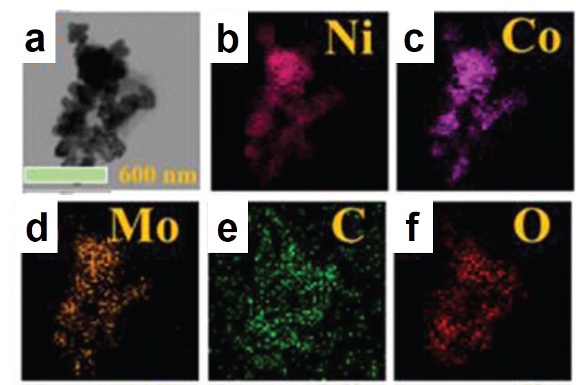
Figure 1. Representative (a) transmission electron microscopy image and (b-f) elemental mappings of the synthesized catalyst.

The catalysts exhibited different catalytic activities dependent on their chemical compositions, which were tunable by varying the moles of the Ni, Co, and Mo precursors. Cyclic voltammograms of various NCM/G all showed markedly increased current density at potentials beyond 0.3 V vs. Ag/AgCl in urea-containing aqueous solutions (Figure 2a), marking their catalytic activity for urea oxidation. Among all the tested catalysts, NCM/G with Ni:Co:Mo = 80:10:10 achieved the largest current density at 0.6 V vs. Ag/AgCl, indicating its highest catalytic activity. Additionally, chronoamperometry demonstrated that increasing the Mo content was beneficial for maintaining catalyst stability, as the current density of NCM/G with the lowest amount of Mo (the black curve in Figure 2b) decayed the fastest. Combining the results of cyclic voltammetry and chronoamperometry, the authors deduced that the optimal molar ratio of Ni:Co:Mo was 80:10:10.

Figure 2. (a) Cyclic voltammograms (scan rate: 1 mV/s) and (b) chronoamperometry (potential: 0.5 V vs. Ag/AgCl) profiles of NCM/G with different Ni, Co, and Mo contents. Electrolyte: 1.0 M KOH + 0.33 M urea in water. The molar ratios of Ni:Co:Mo of NCM/G 90505, 811, and 71515 are 90:5:5. 80:10:10, and 70:15:15, respectively.

The optimization of the chemical composition demonstrated in this work can rationalize the development of high-performance, metallic electrocatalysts for urea oxidation.

For expanded understanding, please read:

Trimetallic NiCoMo/Graphene Multifunctional Electrocatalysts with Moderate Structural/Electronic Effects for Highly Efficient Alkaline Urea Oxidation Reaction

Wei Shi, Xiujuan Sun, Rui Ding, Danfeng Ying, Yongfa Huang, Yuxi Huang, Caini Tan, Ziyang Jia, and Enhui Liu

Chem. Commun., 2020, DOI: 10.1039/D0CC02132F


Tianyu Liu acknowledges Zacary Croft at Virginia Tech, U.S., for his careful proofreading of this post.


About the blogger:

Tianyu Liu obtained his Ph.D. (2017) in Chemistry from the University of California, Santa Cruz, in the United States. He is passionate about the communication of scientific endeavors to both the general public and other scientists with diverse research expertise to introduce cutting-edge research to broad audiences. He is a blog writer for Chem. Comm. and Chem. Sci. More information about him can be found at http://liutianyuresearch.weebly.com/.

Digg This
Reddit This
Stumble Now!
Share on Facebook
Bookmark this on Delicious
Share on LinkedIn
Bookmark this on Technorati
Post on Twitter
Google Buzz (aka. Google Reader)

Teachable micromotors

Micromotors, for the uninitiated aka me, are a specific type of colloidal structure that harvests energy from their environment and turns it into motion. In order for them to be truly effective for possible applications though, they must be able to communicate and coordinate with one another. If you want to make microbots, they can’t just move about all willy-nilly with no regard for each other. Recently, scientists have created a mixed system where one structure sheds silver ions that cause other micromotors to accelerate, an approach that mimics natural systems like bee colonies.

Researchers in China developed a system where photochemically powered micromotors can spontaneously “teach” catalytic micromotors to oscillate without any external influence. The teachers are Janus-type microparticles composed of either polymethylmethacrylate (PMMA) or silicon dioxide particles half coated with silver. Under irradiation with KCl and H2O2, the silver can interconvert between Ag(0) and Ag(1), causing the oscillatory motion of the entire particle. In contrast, the two non-oscillatory micromotors, either polystyrene spheres half coated with platinum (PS-PT) or gold-rhodium microrods (Au-Rh), catalytically decompose H2O2 to move autonomously in standard Brownian motion. When the two types of micromotors are mixed under UV light, the motion of the non-oscillatory materials changes from random to clearly oscillating (Figure 1). The intensity of the motion change depends on the proximity of the learner to the teacher, with learners closer to the teacher displaying more intense oscillations.

Figure 1. Change in movement of non-oscillating micromotors when exposed to oscillating “teacher” structures.

In fact, the Au-Rh rods will demonstrate more intense oscillations than the PMMA-Ag particles. The researchers propose a mechanism where the PMMA-Ag particles release silver ions as they oscillate, which then deposit onto the Au-Rh rods. The silver increases the catalytic activity of the rods and then, given the operating conditions, undergoes the same redox process that causes oscillation in the PMMA-Ag system.

Figure 2. Proposed mechanism of silver release and adsorption onto Au-Rh rods.

This hypothesized mechanism is supported by the development of oscillatory behavior by the Au-Rh rods in under reaction conditions where the PMMA-Ag particles are replaced by silver ions in solution. The silver on the rod surface isn’t merely adsorbed – it forms into small silver nanoparticles which can be seen via electron microscopy, making a new trimetallic structure. These nanoparticles change the trajectories of the rods, causing them to move in circles. While this system isn’t perfect, the student structures have imperfect memories and cannot teach one another, it provides a strategy for working with groups of micromotors to move towards coordinated motion and further applications.

To find out more, please read:

Non-oscillatory micromotors ‘‘learn’’ to oscillate on-the-fly from oscillating Ag micromotors

Chao Zhou, Qizhang Wang, Xianglong Lv and Wei Wang

Chem. Commun., 2020, Advance Article

About the blogger:

Dr. Beth Mundy is a recent PhD in chemistry from the Cossairt lab at the University of Washington in Seattle, Washington. Her research focused on developing new and better ways to synthesize nanomaterials for energy applications. She is often spotted knitting in seminars or with her nose in a good book. You can find her on Twitter at @BethMundySci.

Digg This
Reddit This
Stumble Now!
Share on Facebook
Bookmark this on Delicious
Share on LinkedIn
Bookmark this on Technorati
Post on Twitter
Google Buzz (aka. Google Reader)

Upgrading Methanol Using Zinc-Indium-Sulfide and Solar Light

Based on the chemical formulae, can you figure out how to convert methanol (CH3OH) into ethylene glycol (HOCH2CH2OH)? If you have constantly practiced your organic chemistry, you might have already found the answer: combining two methanol molecules and eliminating one hydrogen molecule (H2). Indeed, this methanol-coupling reaction is a promising, low-cost chemical route to upgrade methanol to chemicals with more carbon atoms. The feasibility of this route, however, is low under mild conditions without catalysts to drive the reaction.

A group of scientists led by Shunji Xie and Ye Wang, both at Xiamen University, China, has developed an environmentally friendly catalyst, Zn2In2S5, for room-temperature methanol coupling to produce ethylene glycol using solar light. This work has been published in Chemical Communications (DOI: 10.1039/c9cc09205f).

The synthesized Zn2In2S5 catalyst is comprised of 1-3 layers of nanosheets. Through a hydrothermal reaction, the researchers first synthesized multi-layer Zn2In2S5 stacks in an aqueous solution (Fig. 1a). Subsequent ultrasonication exfoliated the stacks into few-layer Zn2In2S5­ nanosheets that were confirmed by transmission electron microscopy (Fig. 1b). Zn2In2S5 is a semiconductor and its valence band (VB) resides below the redox potential of ethylene glycol/methanol (Fig. 1c). The band alignment enables Zn2In2S5 to catalyze the oxidation of methanol to ethylene glycol.

Figure 1. (a) A scheme of the synthesis procedures of few-layer ZnmIn2Sm+3 (m=1-3) nanosheets. (b) Transmission electron microscopy images of few-layer Zn2In2S5 nanosheets. (c) Positions of the valence bands (VBs) and conduction bands (CBs) of different metal-sulfide semiconductors.

Zn2In2S5 and its composite exhibited high catalytic activity. Upon irradiation with visible light and solar light (AM 1.5), photo-induced electrons and holes generated in Zn2In2S5 (Fig. 2a). The electrons reduced protons in electrolytes and liberated hydrogen gas, while the holes moved to the Zn2In2S5 surface and split the C—H bond of methanol, forming ·CH2OH radicals. These radicals then dimerized into ethylene glycol. Through depositing a hydrogen evolution co-catalyst, cobalt monophosphide (CoP), and illuminating using AM 1.5 solar light, the authors observed that the CoP/Zn2In2S5 catalyst achieved a rapid formation rate (18.9 mmol gcat-1 h-1) and high selectivity (~90%) of ethylene glycol (Fig. 2b). The yield of ethylene glycol after 12 h of reaction was 4.5%.

Figure 2. (a) A scheme of the formation mechanisms of ethylene (from methanol) and 2,3-butanediol (from ethanol) on Zn2In2S5. EG: ethylene glycol. 2,3-BD: 2,3-butanediol. (b) Formation rates and ethylene glycol selectivity of Zn2In2S5 and CoP/Zn2In2S5 under two illumination conditions. AM 1.5: air mass 1.5 solar irradiance. HCHO is a byproduct.

Zn2In2S5 was demonstrated to effectively catalyze C—H cleavages and C—C couplings of different alcohols, e.g., from ethanol to 2,3-butanediol.


To find out more, please read:

C–H Activations of Methanol and Ethanol and C–C Couplings into Diols by Zinc–Indium–Sulfide Under Visible Light

Haikun Zhang, Shunji Xie, Jinyuan Hu, Xuejiao Wu, Qinghong Zhang, Jun Cheng, and Ye Wang

Chem. Commun., 2020, DOI: 10.1039/c9cc09205f


The blogger acknowledges Zac Croft at Virginia Tech, U.S., for his careful proofreading of this post.


About the blogger:

Tianyu Liu obtained his Ph.D. (2017) in Chemistry from the University of California, Santa Cruz, in the United States. He is passionate about the communication of scientific endeavors to both the general public and other scientists with diverse research expertise to introduce cutting-edge research to broad audiences. He is a blog writer for Chem. Comm. and Chem. Sci. More information about him can be found at http://liutianyuresearch.weebly.com/.

Digg This
Reddit This
Stumble Now!
Share on Facebook
Bookmark this on Delicious
Share on LinkedIn
Bookmark this on Technorati
Post on Twitter
Google Buzz (aka. Google Reader)

Tuning Zeolite Catalysis with Organic Molecules

Zeolites, a class of porous alumina-silicate materials, are industrially critical adsorbents and catalysts. Their highly robust nature and wide range of structural types (over 200!) make them suited to a range of applications. In particular, the general zeolite topology and pore size are selected to match and stabilize the intermediates of a chemical reaction. However, the tunability of zeolites is limited when compared to molecular catalysts, making them more like a solvent than, say, an enzyme. An active field of research is bridging the gap between the robust, scalable zeolites and highly controllable homogenous catalysts. Recent work identified organic residues maintained with the zeolite pores as key in the transformation of methanol to hydrocarbons. Previous fundamental studies demonstrated that a wide range of carbonyl and carbonyl derivative compounds promote the dehydration of methanol to dimethyl ether (DME).

Researchers at BP used methyl mono- and di-carboxylate esters to dehydrate methanol to DME at low temperatures. The mild reaction conditions allowed for high selectivity for DME while eliminating convoluting side reactions. They added either methyl formate or methyl n-hexanoate to a series of zeolite with pores ranging from narrow to wide. At a 5 mol% concentration relative to methanol they saw significant increases in DME production, particularly for the medium and wide pores. Systematic testing of carboxylate chain length found that increasing chain length increased turnovers occurred until methyl n-hexanoate, after which no further benefits were observed as the n-methyl hexanoate had already saturated the catalyst (Figure 1). All proved highly selective for converting methanol to DME with no observed hydrocarbon formation.

Figure 1. Production of DME on a medium-pore zeolite with methyl carboxylate esters of varying chain lengths.

The experimental results were coupled with theoretical work modeling the energetics of the adsorption of the ester onto the zeolite. The calculations showed an increase in adsorption energy with increased chain length, attributed to van der Waals interactions.

Figure 2. Transition state predicted by molecular modeling with methanol attacking the organic promoter adsorbed on the zeolite catalyst.

They also gave even higher energies to molecules with two carboxylate esters, like dimethyl adipate. In fact, the strongly binding molecules produced increased catalysis at loadings as low as 0.001% with respect to methanol. The promoters can be easily switched by changing the input, demonstrating the reversibility of binding at the active site. Additional molecular modeling was used to study possible transition states to develop a catalytic cycle. A proposed transition state involves a direct reaction between the methanol and the organic promotor, however specific evidence has yet to be seen. Additional work examining the role of the water present as a co-adsorbate and its impacts on transition states has yet to be done. Overall, the use of various organic molecules as promotors for the dehydration of methanol to DME on various zeolite catalysts was explored. This represents exciting fundamental study of industrially-relevant chemistry with significant room for future work.

To find out more, please read:

Getting zeolite catalysts to play your tune: methyl carboxylate esters as switchable promoters for methanol dehydration to DME

Benjamin J. Dennis-Smither, Zhiqiang Yang, Corneliu Buda, Xuebin Liu, Neil Sainty, Xingzhi Tan and Glenn J. Sunley

Chem. Commun., 2019, 55, 13804-13807.

About the blogger:

Beth Mundy is a PhD candidate in chemistry in the Cossairt lab at the University of Washington in Seattle, Washington. Her research focuses on developing new and better ways to synthesize nanomaterials for energy applications. She is often spotted knitting in seminars or with her nose in a good book. You can find her on Twitter at @BethMundySci.

Digg This
Reddit This
Stumble Now!
Share on Facebook
Bookmark this on Delicious
Share on LinkedIn
Bookmark this on Technorati
Post on Twitter
Google Buzz (aka. Google Reader)

How does LiNO3 Make Lithium–Sulfur Batteries Long-Lasting?

Lithium–sulfur (Li–S) batteries are rechargeable batteries with elemental sulfur and metallic lithium as the cathode and anode, respectively. These batteries are promising electrochemical energy storage devices because their energy densities are three to five times higher than those of Li-ion batteries. Unfortunately, the practicality of Li–S batteries is hindered by their short lifetimes due to two processes that occur on the Li anode surface: the growth of Li dendrites and the irreversible polysulfide reduction. Adding LiNO3 into battery electrolytes has proven to be useful to prolong battery lifetimes, but the underlying mechanism is uncertain.

In Chemical Communications (doi: 10.1039/c9cc06504k), Sawangphruk and coworkers from Vidyasirimedhi Institute of Science and Technology, Thailand have offered valuable insights to settle the dispute over the effects of LiNO3. The researchers performed theoretical reactive molecular dynamics simulations and elucidated two roles of LiNO3 in Li–S batteries.

The first discovery was that LiNO3 promoted the formation of smooth, double-layered solid electrolyte interfaces (SEIs) on the Li surface. SEIs are thin layers composed of electrolyte-decomposition products, including Li-containing organic compounds and inorganic salts. By simulating the charge distribution near a Li metal surface, the authors mapped the Li-Li radial pair distribution profiles in three phases (Fig. 1a). The similarity between the profiles of the dense phase (the Li metal) and the nest phase evidenced the presence of an amorphous, Li-containing layer atop the Li metal surface. Beyond this amorphous layer was a liquid-like film with Li element distributed homogenously. This double-layered SEI altered the kinetics of Li deposition onto the Li surface upon charging, resulting in smooth and dense SEIs (Figs. 1b and c) that avoided Li dendrite formation.

Figure 1. (a) Li-Li radial pair distribution functions of the dense phase (Li metal), nest phase (the layer atop Li), and disperse phase (the outermost layer). (b and c) Top-view scanning electron microscopy images of the Li metal surface in (b) LiNO3-free and (c) LiNO3-containing electrolytes. Both electrolytes had lithium bis(trifluoromethanesulfonyl)imide (LiTFSI) as a solute, and 1,3-dioxolane (DOL) and 1,2-dimethoxyethane (DME) as solvents.

Another effect of LiNO3 was to capture polysulfide compounds. Through their simulations, the authors deduced the reaction pathways involving the electrolyte molecules, LiNO3 or LiClO4 additives, and lithium polysulfide compounds (Fig. 2a). The concentration of LixNOy, the reduction products of LiNO3 when contacted Li metal, in the LiNO3-containing electrolyte was much higher than those in the additive-free and LiClO4-containing electrolytes. First-principle calculations proved that the highly electro-negative N and O atoms in LixNOy could capture lithium polysulfides via dipole-dipole interactions. This process reduced the likelihood of polysulfide reduction on Li that passivated anodes.

Figure 2. (a) A scheme of the reaction pathways involving the electrolyte, additive, and polysulfide molecules. (b) Product distributions in electrolytes without additives and with LiNO3 or LiClO4.

LiNO3 elongates the lifetimes of Li–S batteries by forming smooth SEIs to impede Li dendrite formation, while maintaining the reactivity of Li anodes by capturing lithium polysulfides.


To find out more, please read:

Insight into the Effect of Additives Widely Used in Lithium–Sulfur Batteries

Salatan Duangdangchote, Atiweena Krittayavathananon, Nutthaphon Phattharasupakun, Nattanon Joraleechanchai, and Montree Sawangphruk

Chem. Commun., 2019, 55, 13951-13954

Tianyu Liu acknowledges John Elliott of Virginia Tech, the U.S., for his careful proofreading of this post.

About the blogger:

Tianyu Liu obtained his Ph.D. (2017) in Chemistry from the University of California, Santa Cruz, in the United States. He is passionate about the communication of scientific endeavors to both the general public and other scientists with diverse research expertise to introduce cutting-edge research to broad audiences. He is a blog writer for Chem. Commun. and Chem. Sci. More information about him can be found at http://liutianyuresearch.weebly.com/.

Digg This
Reddit This
Stumble Now!
Share on Facebook
Bookmark this on Delicious
Share on LinkedIn
Bookmark this on Technorati
Post on Twitter
Google Buzz (aka. Google Reader)

Strengthening Li+-Coordination Decelerates Li-Dendrite Growth in Li-Metal Batteries

Lithium-metal batteries are a family of rechargeable batteries with higher charge-storage capacities than those of lithium-ion batteries. The boosted charge-storage performance of lithium-metal batteries is rooted in its anode material – Li metal, as it possesses an ultrahigh theoretical capacity (3860 mAh/g). However, the growth of dendrites on Li surfaces during charging could short-circuit batteries, cause combustion, and trigger explosions.

A research group led by Feng Li at the Institute of Metal Research, Chinese Academy of Sciences, recently devised a strategy to suppress the notorious Li dendrite growth in lithium-metal batteries. By tuning the composition of the electrolytes, the authors strengthened the coordination between Li+ and electrolyte solvents, which slowed the growth of Li dendrites. This work has been published in Chemical Communications (doi: 10.1039/C9CC07092C).

The researchers introduced an electrolyte additive, tetraethylene glycol dimethyl ether (TEGDME), as a coordination ligand to Li+. Compared to other components in the electrolyte, i.e., 1,2-dimethoxyethane (DME) and 1,3-dioxolane (DOL), TEGDME contains more oxygen atoms that can form multiple, robust coordination bonds with Li+. Specifically, density functional theory calculations showed that the binding energy between Li+ and electrolyte molecules increased by 0.31 eV after introducing TEGDME, reaching an absolute value of 4.93 eV. The enhanced binding force made the separation of Li+ from TEGDME (a prerequisite for Li-dendrite growth) energetically consuming and kinetically sluggish (Figure 1). These characteristics could decelerate Li-dendrite formation and elongate battery lifetimes.

Figure 1. Lithium-dendrite growth in different electrolytes: (a) weak coordination with Li+ promotes fast dendrite growth while (b) strong coordination with Li+ decelerates dendrite formation.

To confirm the above idea, the authors assembled lithium batteries with TEGDME+DME+DOL or DME+DOL electrolytes. Cycling stability tests demonstrated that the battery with the TEGDME-added electrolyte survived 60 charge-discharge cycles at a current density of 1C, whereas the capacity of the battery without TEGDME rapidly decayed beyond 30 cycles under identical testing conditions (Figure 2a). Scanning electron microscopy images revealed that the number of rod-shaped Li dendrites on the anode in the TEGDME-added electrolyte (Figure 2c) was less than that in the TEGDME-free electrolyte (Figure 2b), further confirming that the enhanced cycling stability resulted from the Li-dendrite suppressing effect of TEGDME.

Figure 2. (a) Cycling stability performance of lithium-metal batteries with two different electrolytes. The cathode material in both batteries was lithium iron phosphate (LFP). (b and c) SEM images of the Li anode surface after charging in (b) DME+DOL and (c) DME+DOL+TEGDME electrolytes.

This work highlights the importance of tailoring the electrolyte composition for preserving the stability and safety of lithium-metal batteries.


To find out more, please read:

Suppressing Lithium Dendrite Formation by Slowing Its Desolvation Kinetics

Huicong Yang, Lichang Yin, Huifa Shi, Kuang He, Hui-Ming Cheng, and Feng Li

Chem. Commun., 2019, doi: 10.1039/C9CC07092C

Tianyu Liu acknowledges Xiaozhou Yang of Virginia Tech, the U.S., for his careful proofreading of this post.

About the blogger:

Tianyu Liu obtained his Ph.D. (2017) in Chemistry from the University of California, Santa Cruz, in the United States. He is passionate about the communication of scientific endeavors to both the general public and other scientists with diverse research expertise as a way to introduce cutting-edge research to broad audiences. He is a blog writer for Chem. Commun. and Chem. Sci. More information about him can be found at http://liutianyuresearch.weebly.com/.

Digg This
Reddit This
Stumble Now!
Share on Facebook
Bookmark this on Delicious
Share on LinkedIn
Bookmark this on Technorati
Post on Twitter
Google Buzz (aka. Google Reader)

MOF-Derived Solid-State Lithium-Oxygen Batteries

Just in case you weren’t aware, it turns out that lithium-based batteries are kind of a big deal. While the Nobel-winning batteries have already revolutionized consumer electronics, further development requires batteries with even higher energy densities. Enter: lithium-oxygen batteries (LOBs) with theoretical energy densities of 3500 W h/kg. LOBs come in non-aqueous, aqueous, hybrid, and solid-state varieties based on their electrolytes. Given the previous safety issues for lithium-based batteries with liquid electrolytes (remember the exploding phones?), solid-state electrolytes have attracted substantial research attention. Specifically, Li1+xAlxGe2x(PO4)3, or LAGP, shows promise given its high Li+ transport number and electrochemical stability over a wide window. These solid-state electrolytes need to be combined with new catalytically active high surface area cathode materials that will not react with the lithium and degrade, a persistent issue with MOFs.

Figure 1. Schematic of an assembled all solid-state lithium-oxygen battery.

Researchers in China and Japan have combined LAGP electrolyte with NiCo2O4 (NCO) nanoflakes as the catalytically active cathode material. They then assembled full solid-state batteries, the structure of which is shown in Figure 1, for electrochemical and stability testing. The LAGP was prepared using previously established methods and found to exhibit the expected high stability and lithium mobility. To prepare the nanoflakes, the researchers annealed cobalt-based MOFs on a sacrificial carbon substrate then dipped them in a Ni(NO3)2 solution for nickel doping and annealed once more. This leaves the final nanostructured metal oxide, with the elemental composition confirmed by TEM elemental mapping. As a conveniently freestanding electrode material, the nanoflakes were then loaded in as the cathode.

Once assembled, the researchers tested the full all solid-state LOBs for stability and performance. They demonstrated high discharge capacity and electron transfer efficiency with charge and discharge potentials well within the electrochemical window of the LAGP electrolyte. These are attributable to the high lithium ion mobility and the porous bimetallic nature of the cathode. To confirm that the incorporation of nickel impacted the overall device performance, the pure cobalt nanoflakes were used as the cathode.

Figure 2. Cycling performance of cobalt (left) and cobalt-nickel cathodes (right) at a current density of 100 mA/g.

As seen in Figure 2, the cobalt-only batteries exhibit significant capacity loss in only 35 cycles whereas the NCO cathodes showed no degradation after 90 cycles. While cycling the NCO electrodes, the reversible formation of Li2O2, a common discharge product, occurred in the open pores of the cathode. These pores allow the 500 nm Li2O2 particles to form and dissolve without disrupting the structure of the cathode and give a more stable battery. This research brings completely solid-state lithium-oxygen batteries one step closer to reality.

To find out more, please read:

All solid-state lithium–oxygen batteries with MOF-derived nickel cobaltate nanoflake arrays as high-performance oxygen cathodes

Hao Gong, Hairong Xue, Xueyi Lu, Bin Gao, Tao Wang, Jianping He and Renzhi Ma

Chem. Commun., 2019, 55, 10689-10692.

About the blogger:

Beth Mundy is a PhD candidate in chemistry in the Cossairt lab at the University of Washington in Seattle, Washington. Her research focuses on developing new and better ways to synthesize nanomaterials for energy applications. She is often spotted knitting in seminars or with her nose in a good book. You can find her on Twitter at @BethMundySci.

Digg This
Reddit This
Stumble Now!
Share on Facebook
Bookmark this on Delicious
Share on LinkedIn
Bookmark this on Technorati
Post on Twitter
Google Buzz (aka. Google Reader)

Guiding Light with Molecular Crystals

We’re all used to communications and computing happening at high, and seemingly ever-increasing speeds. Continuing on this trajectory requires the development of materials capable of acting as micro/nanoscale waveguides that don’t experience interference effects from strong external electromagnetic fields. Molecular crystals represent an exciting but relatively under-explored materials class due to their inherently limited emission and absorption properties. However, an international group of researchers recently combined two different crystalline materials with complementary optical properties in a filled-hollow crystal architecture, involving no binding materials or polymer matrices.

Figure 1. Spectra and structure of DCA (left) and PDI (right).

The group used 9,10-dicyanoanthracine (DCA) as the hollow outer crystal, with a perylene diimide derivative (PDI) as the interior compound (Figure 1). When combined, these two compounds exhibit fluorescence that covers the visible and near-IR portions of the electromagnetic spectrum. The researchers grew hollow crystals of DCA with diameters ranging from 50-400 μm in diameter with pores of 10-200 μm and filled them with 1-50 μm PDI crystal fibrils manually by hand(!) (Figure 2) (I honestly can’t imagine how many crystals ended up broken during that experimental learning curve!). The assembled structure for study had a single hollow DCA crystal filled with 18 individual PDI fibrils to create the waveguide.

Figure 2. Schematic of hollow crystal architecture (top) with demonstration of construction (bottom).

When the researchers excited the full structure with a 365 nm continuous wavelength LED, both crystal components emitted light that was guided down to the opposite end. The specific makeup of the spectrum depends on the point of illumination; only the excited compounds emit. This supports the active waveguiding capabilities of the materials. The emissive properties can also be controlled by changing the excitation wavelengths to exclude the absorbance of one of the molecular crystals. PDI can be selectively excited using light above 550 nm and both PDI and DCA act simply as passive waveguides for light in the infrared region of the spectrum, of particular importance for wireless communication. This study represents an exciting next step for organic molecular materials as optical waveguides with a new architecture for devices.

To find out more please read:

A filled organic crystal as a hybrid large-bandwidth optical waveguide

Luca Catalano, Patrick Commins, Stefan Schramm, Durga Prasad Karothu, Rachid Rezgui, Kawther Hadef and Panče Naumov

Chem. Commun, 2019, 55, 4921-4924.

About the blogger:

Beth Mundy is a PhD candidate in chemistry in the Cossairt lab at the University of Washington in Seattle, Washington. Her research focuses on developing new and better ways to synthesize nanomaterials for energy applications. She is often spotted knitting in seminars or with her nose in a good book. You can find her on Twitter at @BethMundySci.

Digg This
Reddit This
Stumble Now!
Share on Facebook
Bookmark this on Delicious
Share on LinkedIn
Bookmark this on Technorati
Post on Twitter
Google Buzz (aka. Google Reader)

1+1>2: Bridging Constituents in Hetero-Structured Hydrogen Evolution Photocatalysts

Solar-driven water reduction is a sustainable method to acquire hydrogen fuel. An indispensable component of this reaction is the photocatalyst which drives spontaneous hydrogen gas evolution from water when illuminated. Hetero-structured materials consisting of two or more catalysts stand out as promising hydrogen evolution catalysts, due to the combined advantages of their constituents (e.g. enhanced light-absorption capability). Unfortunately, the weak adhesion between different components is the Achilles heel of conventional hetero-structured photocatalysts. It impedes electron transport from the photocatalysts to the nearby water molecules, hindering the catalytic activity.

A research group led by Xiao Xiao and Jian-Ping Zou from Nanchang Hangkong University of China has demonstrated a solution to the aforementioned challenge. They firmly connected two photocatalysts – Pt-loaded carbon nitride (CN) and the covalent organic framework CTF-1 – via amide bonds, resulting in a new type of hetero-structured photocatalyst, CN/CTF-1, which exhibited a hydrogen evolution rate approximately 3 times faster than those of conventional hetero-structured photocatalysts made of weakly bound CN and CTF-1.

The researchers adopted a two-step method to synthesize CN/CTF-1. They first reacted CTF-1 sheets with 4-aminobenzoic acid to graft carboxylic groups onto the surfaces of the CTF-1 sheets. A subsequent amide condensation between the amine groups of the CN and the carboxyl groups on the CTF-1 bridged the two components. The amide groups serve as electron transport pathways and facilitate the movement of photo-excited electrons from CTF-1 to CN (Figure 1a) which liberates hydrogen gas.

The covalent amide “bridges” gave CN/CTF-1 a fast hydrogen production rate. Quantitatively, when irradiated with a 300 W Xe lamp at 160 mW/cm2, CN/CTF-1 produced ~4 mmol H2 per gram of CN/CTF-1 after 4 h (0.85 mmol H2 h-1 gcatalyst-1), whereas under identical conditions, weakly adhered CN and CTF-1 sheets as well as a physical mixture of CN and CTF-1 all achieved H2 evolution rates of ~1 mmol H2 per gram of photocatalyst (0.30 mmol H2 h-1 gcatalyst-1) (Figure 1b).

Figure 1. (a) (Pt-loaded) CN sheets are covalently bound to CTF-1 sheets via amide bonds. These covalent bonds serve as electron transport “bridges” that facilitate the diffusion of photo-excited electrons from CTF-1 to CN. (b) H2 evolution rates of four photocatalysts: 1 – covalently bound CN/CTF-1; 2 and 3 –  weakly adhered CN and CTF-1; 4 – a physical mixture of CN and CTF-1.

The covalent bonding strategy is applicable to other coupling reactions such as the Friedel-Crafts reaction. This general method could create a new paradigm for designing and synthesizing high-performance hetero-structured photocatalysts.


To find out more please read:

A General Strategy via Chemically Covalent Combination for Constructing Heterostructured Catalysts with Enhanced Photocatalytic Hydrogen Evolution

Gang Zhou, Ling-Ling Zheng, Dengke Wang, Qiu-Ju Xing, Fei Li, Peng Ye, Xiao Xiao, Yan Li, and Jian-Ping Zou

Chem. Commun., 2019, 55, 4150-4153

About the blogger:

Tianyu Liu obtained his Ph.D. (2017) in Chemistry from University of California, Santa Cruz in the United States. He is passionate about scientific communication to introduce cutting-edge research to both the general public and scientists with diverse research expertise. He is a blog writer for Chem. Commun. and Chem. Sci. More information about him can be found at http://liutianyuresearch.weebly.com/.

Digg This
Reddit This
Stumble Now!
Share on Facebook
Bookmark this on Delicious
Share on LinkedIn
Bookmark this on Technorati
Post on Twitter
Google Buzz (aka. Google Reader)

Using Carbon to Make a Better Solar Cell

Maybe I’m stating the obvious, but solar cells are incredibly complex devices with more components than just the light absorber.

While the focus on the active layer by chemists looking to develop new materials is understandable, in order to truly create next-generation solar cells the other components of the architecture must be improved.  Creating the crack-resistant or resilient layers necessary for functional flexible solar cells is a major challenge currently being addressed. These new materials and approaches also need to work within the general framework of fabrication techniques used for the other layers – ideally at low temperature and solution processible.

An often-neglected piece of the puzzle is the electrode. Electrodes are traditionally composed of a thin metal layer, which is often vapor deposited at high temperatures and low pressures. This class of electrodes is expensive, susceptible to degradation, and can damage the critical hole transport or active layers. One emerging alternative is carbon-based electrodes, applied as pastes. These low-cost, highly stable, and hydrophobic materials are attractive given their compatibility with emerging photovoltaic technologies, particularly perovskites. Their broad application has been limited by the necessity of toxic solvents to create the pastes, but researchers in China have developed a low-temperature, highly conductive carbon paste that can be screen printed onto perovskite solar cells without using toxic solvents.

Fabrication schematic and cross sectional SEM for a perovskite solar cell with a carbon electrode

Figure 1. (a) Fabrication schematic for perovskite solar cells with carbon electrodes and hole transport layers. (b) Cross sectional SEM image of a device.

Not only are the solvents more environmentally friendly compared to those previously used, they also increase the mechanical strength of the final film and, under fabrication conditions, do not damage the perovskite active layer or organic hole transport layer. While the hole transport layer isn’t strictly necessary to create a working device, it has been shown to increase the champion efficiency from 11.7% to 14.55%. This is likely due to poor contact between the perovskite and carbon electrode, which the thin hole transport layer (PEDOT:PSS) helps remedy.

Carbon-based electrode undergoing a bending test and sheet resistivity data

Figure 2. (a) A sample undergoing a bending test. (b) The electrode sheet resistance before and after 100 bends.

The most exciting aspect of these electrodes is their resilience when subjected to a bending test. After 100 bends, the researchers saw no visible film damage or increase in the sheet resistance when compared to the initial sample. Actual flexible solar cells fabricated and studied did show a decrease in performance after 1,000 bends, but this was attributed to known robustness issues in the base ITO layer. This work with carbon-based electrode materials could lead to simpler manufacturing for fabricating perovskite solar cells at a commercial level.


To find out more please read:

A low-temperature carbon electrode with good perovskite compatibility and high flexibility in carbon based perovskite solar cells

Shiyu Wang, Pei Jiang, Wenjian Shen, Anyi Mei, Sixing Xiong, Xueshi Jiang, Yaoguang Rong, Yiwen Tang, Yue Hu & Hongwei Han

Chem. Commun., 2019, 55, 2765-2768

This article is also part of the Chemical CommunicationsPerovskites‘ themed collection.

About the blogger:


Beth Mundy is a PhD candidate in chemistry in the Cossairt lab at the University of Washington in Seattle, Washington. Her research focuses on developing new and better ways to synthesize nanomaterials for energy applications. She is often spotted knitting in seminars or with her nose in a good book. You can find her on Twitter at @BethMundySci.

Digg This
Reddit This
Stumble Now!
Share on Facebook
Bookmark this on Delicious
Share on LinkedIn
Bookmark this on Technorati
Post on Twitter
Google Buzz (aka. Google Reader)