Author Archive

Reusable, robust NanoPort connections to PDMS chips

Jesse Greener, Wei Li, Dan Voicu and Eugenia Kumacheva
Department of Chemistry, University of Toronto, 80 St. George Street, Toronto, Ontario, Canada

Why is this useful?


Typical fluidic connections to PDMS chips consist of tubing inserted into a punched inlet, held in place by glue, for example, a cured epoxy glue. These connections can fail at low pressures because of weak adhesion of the glue to PDMS. In addition, insertion of the tubing directly into the inlet may affect the flow if the tubing is pushed right to the bottom of the channel, thereby increasing hydrodynamic resistance. This is particularly a problem for microchips made from a thin layer of PDMS. Furthermore, even subtle changes to hydrodynamic resistance at the inlet can affect flow rates from pressure-driven sources or cause differential flow rates through inlets which are supplied from a manifold that is being driven from a single source.

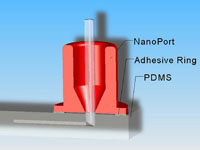
Upchurch has devised a low fluidic resistance chip connection system made from the polymer PEEK called a NanoPort, which can easily accommodate new feeds via a threaded nut and ferrule system.[1] However, this device is designed as a single-use port which is sealed to the chip via a permanent bond at its base using an adhesive ring. The adhesive ring does not stick well to untreated PDMS but plasma treatment of the fully cured PDMS surface has been reported to enhance the bond between the NanoPort/adhesive ring assembly and PDMS.[2] This technique has the advantage of being able to handle working pressures of between 30-50 PSI, but suffers from the single use nature of the adhesive ring. For connections to PDMS chips, Upchurch recommends that the NanoPort be imbedded in the PDMS during microchip curing. This technique is not ideal because the sealing surface area is relegated to the bottom of the NanoPort only, and the semi-cured state of the PDMS is not conducive to creating a strong bond. Other groups have fabricated their own, low cost PDMS connectors, which may be a convenient substitute for the NanoPort in low pressure applications.[3]

This tip reviews an alternative approach; encasing the NanoPort in PDMS at the surface of a previously cured PDMS microchip. Benefits include NanoPort reusability (after liberating them from the PDMS encasing) and higher useable pressure ranges (we determined that up to 85 PSI can be achieved). This technique can be easily adapted to chips of any materials which make a strong bond with PDMS, including glass and polycarbonate.

What do I need?


  • PDMS SYLGARD 184 silicone elastomer base & curing agent (Dow Corning)
  • Upchurch NanoPort assembly
  • Plasma cleaning system for PDMS surface oxidation
  • A heat source (convection oven)
  • One 3 cm-long piece of tubing with 1.59 mm OD (1/16 inch) per inlet
  • Knife or 2 differently sized cork borers, the smallest of which should be at least 1.0 cm (we used 1.7 and 1.0 cm diameter)

What do I do?


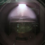
1. Prepare the PDMS chip, ensuring that access holes with diameter of roughly 1.5 mm are punched into the surface.

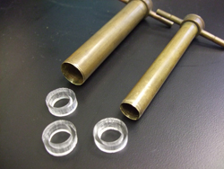
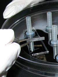
2. Punch or create PDMS rings with thickness no less than approximately 5 mm.

Figure 1

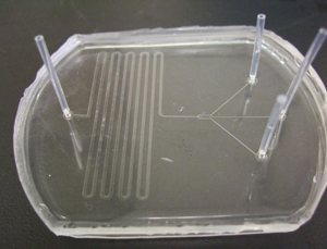
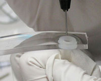
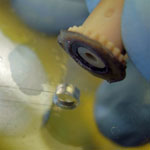
3. Insert 1/16 inch OD tubing into the inlet holes to block PDMS from entering the device.

Figure 2

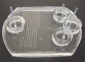
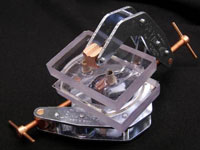
4. Plasma bond the PDMS rings centered around the inlet holes on the PDMS chip (we use 90 seconds at 600 mTorr). This serves as a reservoir for liquid PDMS for the following steps.

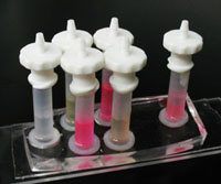
Figure 3

5. Coat the bottom of the reservoir with less than 1 mm of liquid PDMS, then place the NanoPort base over the tubing in the PDMS reservoir. Make sure at this stage that no air bubbles are trapped at the bottom of the NanoPort in the groove designed for the o-ring, which we are not using for this application. This can be accomplished by rotating the port’s base in the liquid PDMS within the reservoir while sliding it up and down slightly around the tubing to allow air to escape. Degassing under vacuum may also work.

6. Finish filling the reservoir with PDMS, being careful not to get any in the threaded area of the NanoPort or inside the tubing, and heat cure (we used 4 hours at 74ºC).

7. After curing, pull the tubing out of the inlet. If any PDMS leaked into the threaded part of the NanoPort base this can be removed with tweezers or by repeatedly connecting and disconnecting the base’s male threaded counterpart (nut). Clear debris with compressed air.

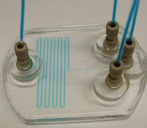
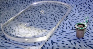
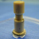
8. Connect the nut and ferrule (or coned nut) to 1/16 OD tubing, attach to the NanoPort base and supply liquid or gas to the chip.

Figure 4

What else should I know?


In this example, we apply this technique to mounting NanoPorts on to a PDMS microchip. In theory, other substrates can benefit from this technique as long as they can be bound to PDMS either by plasma treatment, or by curing liquid PDMS to it. Also, the PDMS ring provides a leak-proof reservoir for liquid PDMS which results in a clean finish when affixed to the surface via plasma treatment. However, rings can also be stuck to the surface via curing a thin coat of liquid PDMS between the two, though the finish may not look as nice.

Our pressure tests probed the strength of the bond between the NanoPort and PDMS. Therefore a flat piece of PDMS substrate was used instead of a microchip with channel structures. By progressively increasing the pressure of an inert gas (N2) being supplied to the NanoPort assembly it was determined that in every case the failure occurred between its base and the top of PDMS substrate. In our tests, failure occurred between 40 and 85 PSI. In theory, the assembly would benefit from more contact area between the PDMS/NanoPort assembly and the PDMS chip. A wider PDMS reservoir would accomplish this, though inlet spacing would have to be adjusted to account for the larger assembly footprint over each inlet. In addition, changing the ratio of silicone elastomer to curing agent and/or implementing this technique on a surface that has not yet fully cured or has been freshly plasma treated may also help to strengthen this bond. The same NanoPorts used in previous tests were then attached to a working microfluidic chip and subjected to increasing gas pressure. In this case, the chip itself separated before the reusable NanoPort connection failed.

References


[1] http://www.upchurch.com/PDF/I-Cards/N4.PDF
[2] C. Koch, J. Ingle, and V. Remcho,  Bonding Upchurch® NanoPorts to PDMS, Chips & Tips (Lab on a Chip), 12 February 2008.
[3] S. Mohanty, D. J. Beebe and G. Mensing, PDMS connectors for macro to microfluidic interfacing, Chips & Tips (Lab on a Chip), 23 October 2006.

Digg This
Reddit This
Stumble Now!
Share on Facebook
Bookmark this on Delicious
Share on LinkedIn
Bookmark this on Technorati
Post on Twitter
Google Buzz (aka. Google Reader)

Rapid prototyping of a PMMA microfluidic chip with integrated platinum electrodes

Martin Arundell, Adai Colom Diego, Óscar Castillo, and Josep Samitier
Nanobioengineering group, Institute for Bioengineering of Catalonia (IBEC), Baldiri Reixac 10-12, 08028 Barcelona, Spain

Why is this useful?


This is a very quick and useful method for researchers who do not have access to high tech micro-fabrication facilities and want to try out an idea or a test in a quick, cheap and simple fashion. In this case it is for those of us who want to test certain techniques such as in-channel electrochemical, conductivity or impedance measurements. It also saves time and costs from using high tech fabrication techniques and will aid the researcher in future designs that can then be fabricated the more conventional way in a clean room. In addition, it is a cheap and effective way of introducing undergraduate and masters students to various chip techniques.

What do I need?


  • An oven that will go up to about 150 °C
  • Metal clamp with smooth surfaces (the clamp surfaces should be at least 25 by 50 mm). Obviously this depends on the size of the chip you require.
  • Tungsten 125 µm wire (Advent) and a pair of good pliers
  • Platinum 50 µm wire  (Advent)
  • PMMA 500 µm thick sheets (Goodfellow)
  • Solder
  • Araldite 2014 epoxy adhesive Glue
  • Stanley (utility) knife

What do I do?


1. The first thing to do is to cut the PMMA sheets depending on the sizes you require and your clamp size.

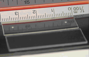
2. Two 1 mm holes should then be drilled on either side of the PMMA device depending on the length of the channel required as shown in Figure 1.

Figure 1

3. Approximate where you would like to place your electrodes and make small slits with a Stanley knife on either edge of one of the PMMA pieces. The number of slits you make depends on how many electrodes you require for your device.

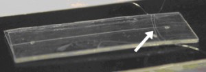
4. The next step is to place the electrodes (as many as you require) onto the chip and carefully position them into the slits, indicated by the arrow in Figure 2. We used 50 µm platinum wires but any size can be used. The larger the wire the easier it is to place the wires on the chip.

Figure 2. Slits containing the integrated electrodes

5. Then heat up a soldering iron and lightly touch one of the sides of the PMMA chip where the wires are placed in the slits. The soldering iron heats up the wire and slightly melts the PMMA, making it more snug in the slit. This will hold the wire in place and allow you to pull it taught to the other side where it can be permanently bonded in the other PMMA slit. Repeat this step for each electrode.

6. Although the wires are taught it is still possible to re-position them slightly (using the tweezers) depending on the required gap. We were able to get inter-electrode distances down to about 50 µm.

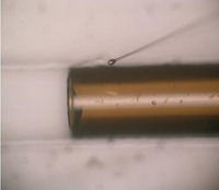
7. The next step is to make a channel and we used a 125 µm tungsten wire (straight cut lengths) for this. See Figure 3.

Figure 3. The tungsten wire (arrow) is positioned with respect to the reservoir holes. The small pieces of tape were used to temporarily keep the two pieces of PMMA together before the fabrication procedure in step 8

8. To make the clamping of the device more simple the procedure below should be followed. First, the clamp should be placed on one end so that the PMMA piece with the integrated electrodes can be easily placed on the bottom part of the clamp. The tungsten wire can then be placed on top of the integrated electrode PMMA piece and then a blank PMMA piece placed on top of this. The tungsten wire can then be positioned into place so that it lines up with the drilled holes. The clamp can then be firmly tightened and placed in a pre-heated oven at 140 °C. After 5 minutes the clamp is re-tightened and placed in the oven for a further 10 minutes.

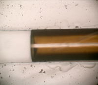
9. The PMMA device can then be removed from the oven and the bonded chip can be removed from the clamp. The tungsten wire can then be removed from the PMMA device and glue can be applied to seal up the open end. When the wire was removed from the PMMA device a channel was formed without disturbing the electrode array. This was carried out a number of times with good reproducibility.

10.  Figure 4 shows the resulting channel with integrated electrodes.

Figure 4a. The channel and integrated electrodes (arrow).

Figure 4b. Zoomed-in view of the two electrodes crossing a microchannel. In this case the approximate distance between the 2 electrodes is 260 µm.

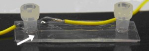
11. Wires can then be attached by using a solder or silver epoxy to the platinum electrode wires. To strengthen the connections it is best to glue the insulation part of the connecting wires to the body of the PMMA, as shown in Figure 5.

Figure 5. Chip with integrated electrodes (arrow) and glued connecting wires.

What else should I know?


The devices fabricated using the method above were tested using capillary electrophoresis and pressure-driven flow. In both cases they worked very well and the performance of the electrodes was tested using impedance measurements. This worked well by injecting a 1:10 diluted PBS buffer into a concentrated PBS buffer solution and measuring the change in conductivity. No leakages were observed and a good signal resulted from the test. In addition, using the same method, it was also possible to fabricate the chips with cross channels for electrophoretic injection. The cost of materials was approximately €200 for 5 of the 300 x 300 mm x 500 µm thick PMMA sheets from Goodfellow. The 50 µm platinum wire (5 m in length) was ordered from Advent and cost approximately €120 and the 125 µm tungsten straight short wires cost approximately €80 for 100 pieces. Total cost for the wires is about €400 which would make about 100 chips at an approximate cost of €4.00 per chip.

Digg This
Reddit This
Stumble Now!
Share on Facebook
Bookmark this on Delicious
Share on LinkedIn
Bookmark this on Technorati
Post on Twitter
Google Buzz (aka. Google Reader)

Bonding & sealing of components in PDMS by deposition of micro-drops of PDMS using micropipette

Arash Noori and P. Ravi Selvaganapathy
Department of Mechanical Engineering, McMaster University, Hamilton, Ontario, Canada

Why is this useful?


Sealing and bonding of components in PDMS (poly-dimethylsiloxane) molds using PDMS as glue is as challenging as it is effective because of the ability of PDMS glue to conform to nanometer sized features.  An ever present problem is the flow of the uncured PDMS into undesired locations because of the deposition of large drops and the low viscosity of PDMS.  This can lead to clogging of interconnects, channels and on-chip components in the assembly process thus damaging the device or necessitating repair.

This tip presents a method for the deposition of microdrops of uncured PDMS using a micropipette and probe station micromanipulator to allow for highly controlled and localized sealing and bonding.  This process can be used to seal interconnects in critical regions, to repair cracks and to bond components into microfluidic devices.  It can be used for any process that requires highly localized deposition of PDMS to act as glue or sealant.  For demonstration purposes this article will describe the process to embed and seal a 360 µm OD/20 µm ID fused silica capillary into a PDMS microfluidic device without clogging the opening.

What do I need?


  • Fully cured PDMS microfluidic device
  • Sylgard 184 silicone elastomer kit (Dow Corning)
  • Probe station with microscope and micromanipulator probe
  • Micropipette puller and borosilicate glass tubes (1 mm OD/0.5 mm ID, Sutter Instrument Company, California, USA) to fabricate micropipettes (may also be purchased from WPI Inc, Florida, USA)
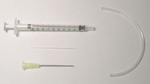
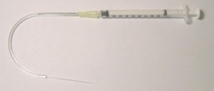
  • Syringe (1 ml), needle (20G1½) and tubing (Tygon 2.4 mm OD/0.7 mm ID) (Figure 1)
  • Epoxy
  • Source of heat (hotplate or oven)

Figure 1

What do I do?


1. Connect the un-pulled end of the micropipette and the needle to opposite ends of Tygon tubing and seal using epoxy. (Figure 2)  The tubing should be long enough to allow for pumping of the PDMS without disturbing the micropipette tip.

Figure 2

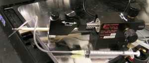
2. Carefully attach the micropipette to the probe station micromanipulator tip using adhesive tape.  Make sure that it is firmly attached to the probe. (Figure 3)

Figure 3

3. Place the PDMS device onto the probe station and locate the place where deposition of the microdrops of PDMS is desired.  Refocus and move the micropipette tip to the centre of the viewing area of the microscope.

4. Withdraw a small amount (<1 ml) of 1:30 ratio PDMS into the syringe and connect to needle.

5. Very slowly begin injecting PDMS into the tubing and micropipette, monitoring the movement of the PDMS in the micropipette until a drop of PDMS is visible at the micropipette tip.

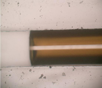
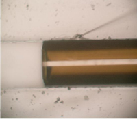
6. Refocus the microscope to the PDMS substrate below and bring the deposition area in alignment with the micropipette tip.  Slowly start moving the probe station micromanipulator tip down until both the PDMS substrate and the micropipette are visible.  Readjust the micropipette tip to the desired location using the micro adjusters.  Slowly move the micropipette tip down.  Once the micropipette tip makes contact with the PDMS substrate pause and let the PDMS drop flow into the desired region.  More PDMS can be deposited by gently applying pressure to the syringe to cause more flow of PDMS to the deposition area. (Figure 4)

7. After deposition is complete, place the covered PDMS substrate onto a hotplate at ~95 ºC and cure for 10 minutes.

Figure 4a

Figure 4c

Figure 4b

Figure 4d

References


http://www.tygon.com/
http://www.dowcorning.com/
http://www.sutter.com/
http://www.wpiinc.com/

Digg This
Reddit This
Stumble Now!
Share on Facebook
Bookmark this on Delicious
Share on LinkedIn
Bookmark this on Technorati
Post on Twitter
Google Buzz (aka. Google Reader)

Lamination of plastic microfluidic devices

Daniel Olivero and Z. Hugh Fan
Department of Mechanical and Aerospace Engineering, University of Florida, Gainesville FL, USA

Why is this useful?


Bonding is a critical step in fabricating plastic microfluidic devices.[1] It is a process to seal microfeatures (e.g. channels) in a plastic substrate with a cover film. Lamination is one of the best methods to achieve a successful bond, with no air bubbles between the plastic substrate and film, no distortion of microfeatures, and minimum deformation of the device.[2] The parameters affecting the quality of lamination include the heating temperature, the pressure placed on the assembly, and the lamination process.[2] This tip describes using a commercially available, tabletop, roller laminator to seal a plastic substrate with a cover film. The plastic substrate (1.5 mm thick) is made from a cyclic olefin copolymer (COC) resins (Zeonor® 1020) and the film is a 100 µm thick COC film (Topas® 8007).

What do I need?


  • A plastic substrate with microchannels (1″ x 3″)
  • A thin film (1″ x 3″)
  • Metalized Mylar films
  • A hot plate
  • A conventional laminator (GBC® Catena 35, Lincolnshire, IL)

The set up


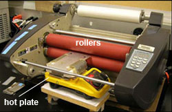
Figure 1.

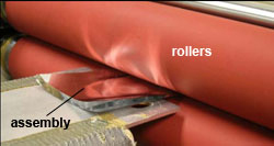
To preheat the plastic substrate to a temperature close to the lamination temperature, the laminator is modified as follows. The feed table in front of the rollers is removed and replaced with a hot plate as shown in Figure 1. The hot plate is raised to align the plate surface with the gap between the two rollers. The hot plate is used to preheat the plastic substrate so that it is easier to reach the required temperature for lamination of COC devices.

What do I do?


1. Clean both the plastic substrate and the cover film in purified water in an ultrasonic bath. Then rinse them in acetone and dry them in a clean air in a laminar hood. Make sure that both the substrate and the film are completely dry before proceeding.

2. Assemble the plastic substrate with the cover film. In our case, alignment is not required since all features are in the substrate. If any feature is made in the cover film, accurate alignment is likely needed.

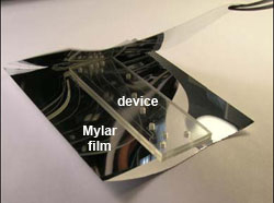
Figure 2.

3. Cut two pieces of Mylar sheets sufficiently large to cover both the plastic substrate and the cover film. Place them between two Mylar sheets as shown in Figure 2. The Mylar sheets are used to prevent the texture of the rollers from being transferred to the plastic device, maintaining a smooth surface of both substrate and film.

Figure 3.

4. Place the assembly of the plastic substrate, the cover film and the Mylar sheets on the hot plate. Make sure that the cover film is at the bottom side, so that the heat is easier to be transferred to the interface between the film and substrate. Place a microscope slide and weights (2 x 44 g) on top of the assembly to ensure the assembly is in contact with the hot plate, as shown in Figure 3. The slide allows a uniform pressure placed on the assembly. For the specific plastic substrate and film, the hot plate is set at a temperature of 73ºC. Other plastic materials likely require different temperatures as discussed in the literature.[2,3]  Allow the assembly to be heated for four minutes.

Figure 4.

5. After the completion of the pre-heating, remove the weights and the slide from the assembly. The laminator rollers should have been heated to a temperature of 124ºC. The gap between the rollers is set at 3 mm and the roller speed is set at 3 feet/minute. Press the “run” button of the laminator and gently slide the assembly into the rollers. Make sure that the plastic substrate and the film do not become misaligned while sliding. Once the assembly enters the rollers it should move by itself through the laminator as shown in Figure 4. If needed, the device may be rolled through the laminator once more to ensure a complete lamination.

6. Once completed a functional microfluidic device is obtained, as shown in Figure 5. This device was used for two-dimensional protein separation by integrating isoelectric focusing (IEF) and polyacrylamide gel electrophoresis (PAGE).[4] The device was filled with a dye for easy visualization of channels. Note that this lamination method can be used for other types of materials but the variables such as the lamination temperature likely need to be adjusted for a perfect lamination.

Figure 5. Cyclic olefin copolymer device

Acknowledgements


This work is supported in part by the grants (48461-LS and 52924-LS-II) from the USA Army Research Office and the startup fund from the University of Florida.

References


[1] L. J. Kricka, P. Fortina, N. J. Panaro, P. Wilding, G. Alonso-Amigo and H. Becker, Lab Chip, 2002, 2, 1-4.
[2] C. K. Fredrickson, Z. Xia, C. Das, R. Ferguson, F. T. Tavares and Z. H. Fan, J. Microelectromech. Syst., 2006, 15, 1060-1068.
[3] M. L. Hupert, W. J. Guy, S. D. Llopis, H. Shadpour, S. Rani, D. E. Nikitopoulos, S. A. Soper, Microfluid. Nanofluid., 2007, 3, 1-11.
[4] C. Das, J. Zhang, N. D. Denslow, and Z. H. Fan, ZH. Lab Chip, 2007,  7, 1806-1812.

Digg This
Reddit This
Stumble Now!
Share on Facebook
Bookmark this on Delicious
Share on LinkedIn
Bookmark this on Technorati
Post on Twitter
Google Buzz (aka. Google Reader)

Quick measurement of electroosmotic flow velocity

Motohiko Nohmi, Fluid Machinery Research Center, EBARA Research Co., Ltd., Japan
Juan G. Santiago, Mechanical Engineering Department, Stanford University, CA, USA

Why is this useful?


We present a simple way of estimating electroosmotic flow velocities in channel geometries with at least one intersection.  The method is useful where a well-defined electrokinetic injection of a discrete plug of a neutral dye (the typical method, [1]) is not easily obtained given available equipment (e.g., when working with a primitive voltage sequencer or an insensitive CCD).

What do I need?


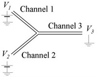
  • Microfluidic device with at least one intersection (Fig. 1)
  • CCD/CMOS camera
  • Epi-fluorescence microscope
  • Voltage control device that can switch potentials at two nodes
  • Neutral dye (e.g., 100 µM Rhodamine B)
  • Chemical buffers

Figure 1. Electrokinetic microchannel device with a simple Y-Channel topology. The end-channel potentials are V1, V2, and V3.

What do I do?


1. We assume here that the channel is expected to have a negative wall charge, but simple observations with a fluorescent solution can confirm this.  We add dyed solution to reservoir 1.  For a symmetric network (e.g., Fig. 1), keeping the sum V1+V2 constant will maintain a uniform electric field in the outlet Channel 3.

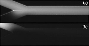
2. As a preliminary observation, vary V1 and V2 and test the limits which will initiate reverse flow in channels 1 or 2. Figure 2 shows example limits for a given maximum potential of (a) V1 = 1175 V, V2 = 925 V and (b) V1 = 925 V, V2 = 1175 V.  We’ll refer to these voltage limits as V1,high, V2,low, V1,low and V2,high.  (See [2] for predicting these voltages.)

Figure 2. Given a maximum (convenient) voltage limit V1,high = V2,high, voltages V1 and V2 can be adjusted to find suitable combinations of V1 and V2 which lead to zero back flow. (a) V1,high and V2,low (b) V1,low and V2,high.

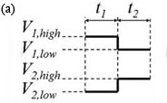
3. The voltage controller should alternate V1 and V2 as shown in Fig. 3(a).  Experiment with t1 and t2 so that the flow has a noticeable disturbance propagating into channel 3 as shown in the movie of Fig. 3(b) (download below).  In Fig. 3(b), t1 and t2 are both 1 s, Vhigh = 1100 V, Vlow = 900 V and the image sequence was captured with 50 ms exposure time and 64.6 ms time-between-frames.

Figure 3. (a) One cycle of control voltages V1 and V2.  The duration of each of the two states is t1 and t2, respectively (typically t1 = t2).  Triangular or sinusoidal waves can be used, but require better equipment and a more complex setup.  (b) Visualization of flow showing propagation of disturbances flowing down channel 3 (see video below).

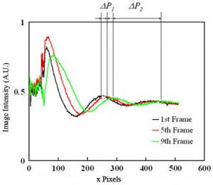
4. Capture an image sequence of modulated flow near the entrance of channel 3 (4-5 periods should be enough).  Extract the values of image intensity along the approximate centerline of the channel.  For better results, average a few pixel rows centered along the channel centerline.  Fig. 4 shows raw data for the dye intensity of the centerline of the 1st, 5th and 9th frame of an image sequence of the movie of Fig.3(b).  For a simple velocity estimate, analyze the second peak into the channel (where the velocity field is approximately parallel and fully developed).  From the two traces in Fig. 4, peak displacement over three frames is about Capital DeltaP1 = 20 pixels or u=k*Capital DeltaP1/Capital Deltatf= 131 µm/s (Eq. (1)).  Here k is the number of imaged microns per pixel, Capital DeltaP1 = 20 pixels , and Capital Deltatf is the time interval of the movie frame. You can also estimate velocity from the wavelength of the disturbance (and the known cycle time, 2 s):  u=k*Capital DeltaP2/(t1+t2)= 138 µm/s (Eq. (2)).  Here, Capital DeltaP2 (= 165 pixels) is the length between two dye peaks in a single image and t1+t2  is the cycle time of voltage modulation. These two approximate velocity measurements typically agree to within about 8%. The latter method is particularly useful when only a single image is available.

Equation (1).

Equation (2).

Figure 4. Dye intensity along the centerline of the 1st, 5th and 9th frames of of an image sequence of the propagating wave near the inlet of channel.

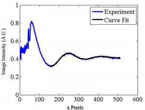
5. The methods described above are susceptible to noise in the image data, among other factors.  A more reliable technique uses multiple measurements and ensemble averages.  One way to accomplish this is using a fitting routine to analyze the waveform of Fig. 4.  We choose the following function:

Equation (3).

The coefficients of Eq. (3) can be estimated for each movie frame as shown in Fig. 5 (download below) by using the Gauss-Newton nonlinear least-squares data fitting routine “nlinfit” in MATLAB. The averaged wavelength Capital DeltaP2ave is calculated as 2Pi/C3ave  = 166.8 pixels and the averaged velocity is calculated as 140 µm/s using Eq. (2).  The velocity is also determined from the phase velocity C4 in Eq.(3) as follows.

Equation (4).

In Eq. (4), dC4/dt is calculated using a linear regression fit of the C4 data vs. time for 200 images. C4 changes linearly in time, and the phase velocity dC4/dt can be calculated by using a linear regression fit of the C4 data vs. time for 200 images. The wave travels one wavelength for the time of 2Pi/(dC4/dt), so the velocity of the fluid is determined as the averaged wavelength divided by 2Pi/(dC4/dt) as described in Eq. (4).

Figure 5. Spatial image intensity variation along channel centerline for a single image as a function of distance along the separation channel (in pixels). Shown with the data is a curve of the form of Eq. (3). (See .avi file below).

References


[1] S. Devasenathipathy and J. G. Santiago, “Electrokinetic Flow Diagnostics” in Micro- and Nano-Scale Diagnostic Techniques, ed. K. Breuer, New York, Springer Verlag, 2004.
[2] K. V. Sharp, R. J. Adrian, J. G. Santiago, and J. I. Molho, “Liquid Flows in Microchannels” in CRC Handbook of MEMS, ed. M Gad-el-Hak, CRC Press, New York, 2001, pp. 6-1 to 6-38.

Related links


Figure 3b .avi file
Visualization of flow showing propagation of disturbances flowing down channel 3.

Figure 5 .avi file
Spatial image intensity variation along channel centerline for a single image as a function of distance along the separation channel (in pixels).

Digg This
Reddit This
Stumble Now!
Share on Facebook
Bookmark this on Delicious
Share on LinkedIn
Bookmark this on Technorati
Post on Twitter
Google Buzz (aka. Google Reader)

See where to punch holes easily in a PDMS microfluidic device

Amy C. Rowat and David A. Weitz
Dept. of Physics/Harvard School of Engineering and Applied Sciences, Harvard University, Cambridge, MA, USA

Why is this useful?


The microfluidic channels in PDMS devices are connected to the macroscopic world by inserting tubing into the inlet holes of flow channels.  We make inlet holes by punching through the PDMS with a razor-sharp biopsy punch to remove a piece of PDMS similar in diameter to the tubing.  However, it is often difficult to see where to punch this hole, especially when channels are shallow in height.  Here we present a tip that makes it easy to see where to punch inlets in PDMS devices by putting a ring light source beneath the device; because the channels scatter the light, the inlets are easy to see.

What do I need?


  • PDMS mold
  • biopsy punch (0.75 mm for PE20 tubing, Harris Uni-Core, Ted Pella, Inc., Redding, CA)
  • piece of glass (borosilicate plate or glass microslide)
  • ring light (Dolan-Jenner Industries, Inc.) [Note: many dissecting scopes are equipped with a ring light; a homebuilt apparatus could also be used.]
  • isopropanol

What do I do?


  1. Peel the PDMS off the master wafer.
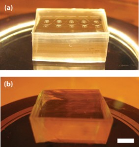
  2. Invert the ring light and place the glass slide on top.  [We use the light source from the dissecting scope in our cleanroom.]  Then place the PDMS device on the glass slide with the channels facing upwards (Figure 1).  By moving the device to different positions on the glass plate, different angles of backlighting result making it easier to see the inlets and channels.
  3. When you have located the correct position of the inlet, press the biopsy punch through the PDMS so that it contacts the glass, then turn the punch one quarter clockwise.  Lift the PDMS off of the glass surface, the then depress the button on the biopsy punch to release the PDMS plug.  Be sure that the plug detaches from the device; sometimes the plug can get stuck and obstruct the inlet hole.
  4. Rinse the device thoroughly with isopropanol.  Chunks of torn PDMS get stuck in the holes, so it is important to flush them with solvent.  Dry with filtered air.
  5. Plasma treat the PDMS, bond to glass, and insert tubing.

Figure 1. (a) A glass slide placed on top of an inverted ring light creates a platform that makes it easy to see where to punch holes in a PDMS microfluidic device. The device shown here has channels of 4.5 µm height. (b) In the absence of backlighting, the channels are difficult to see. Scale, 5 mm.

What else should I know?


In addition to backlighting, it also helps to fabricate a pattern in or around the inlet that scatters light.  We typically use a pinwheel pattern inside the hole as well as lines radiating out from the holes as shown in Figure 1.

Digg This
Reddit This
Stumble Now!
Share on Facebook
Bookmark this on Delicious
Share on LinkedIn
Bookmark this on Technorati
Post on Twitter
Google Buzz (aka. Google Reader)

An easy temperature control system for syringe pumps

Lorenzo Capretto, Stefania Mazzitelli and Claudio Nastruzzi
Department of Chemistry and Technology of Drugs, University of Perugia, Perugia, Italy

Why is this useful?


The most common way to pump liquid into microfluidic devices is by syringe or peristaltic pumps. Syringe pumps are usually preferred for their ease of use and for the most accurate and stable control of the flow rate. In addition, syringe pumps allow the use of disposable and sterile syringes very much facilitating all the protocols involving cells that require sterile conditions.

On the other hand, syringe-pumps have the disadvantage that regulating the temperature of the pumped liquid is difficult. This feature is particularly relevant for a number of microfluidic applications when the temperature of one or more liquid phases, pumped through the chip, should be strictly controlled. For instance, manipulation of animal cells (movement, sorting or encapsulation) usually requires a maintained temperature of 37°C. Moreover many protocols involving the use of polymers or labile compounds need controlled temperatures either below 0°C or above 40-50°C.

We propose a tip that, in an easy and cheap way, solves the problem of temperature control when using syringe-pumps, no matter which type of microfluidic devices are used.

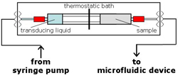
The general idea depends on the use of two coupled syringes (see Fig. 3B) acting as a pressure transducing system. The two coupled syringes, assembled as reported in the general scheme (Fig. 5), can be easily maintained at a fixed temperature by a cheap and flexible thermostatic bath, allowing liquid to be pumped into the chip at a constant, controlled temperature.

What do I need?


  • 1-30 mL polypropylene syringes (Artsana, Italy)[1]
  • Clips for conical joints KECKT (for 5 mL syringes use KECKT KC 14, Schott Duran, Germany, No.: 29 031 00)[2]
  • Teflon® FEP Tubing, 1/8″ OD (Upchurch Scientific, UK; No.: 1523)[3]
  • Quick Connect Luer Adapters, Female Luer to 1/4-28 Female (Upchurch Scientific, UK; No.: P-658)[3]
  • Nuts, for 1/8″ OD tubing (Upchurch Scientific, UK; No.: P-345)[3]
  • Flangeless Ferrules, for 1/8″ OD tubing (Upchurch Scientific, UK; No.: P-300)[3]
  • Standard Polymer Tubing Cutter for 1/16″ and 1/8″ OD tubing (Upchurch Scientific, UK; No.: A-327)[3]
  • Coping saw (X-ACTO, USA)[4]
  • Thermostatic bath equipped with a DC10 Immersion Circulator (Thermo Haake, Germany, No.:426-1001)[5] and with a screw clamp for a plexiglass bath (15x40x15 cm)

What do I do?


The procedure below refers to the assembly of a transducing system based on the use of 5 mL syringes.

1. Saw or cut the plungers of the two syringes, one at 1.5 cm from the plug (sample syringe) and the other at 6.5 cm from the plug (transducing syringe).

Figure 1.

2. Insert the longer plunger of the transducing syringe into the barrel of the sample syringe.

Figure 2.

3. Fix the barrels of the transducing and sample syringes with a KECK clip.

Figure 3.

4. Insert the Luer lock port for both transducing and sample syringes.

Figure 4.

5. Place the two syringe assembly into the thermostatic bath.

6. Operate the system following the general assembly scheme reported in Fig. 5A.

Figure 5A

Figure 5B

References


[1] www.artsana.com
[2] www.duran-group.com
[3] www.upchurch.com
[4] www.xacto.com
[5] www.thermo.com

Digg This
Reddit This
Stumble Now!
Share on Facebook
Bookmark this on Delicious
Share on LinkedIn
Bookmark this on Technorati
Post on Twitter
Google Buzz (aka. Google Reader)

Integrated reservoirs for PDMS microfluidic chips

T. Liu, E. V. Moiseeva, and C. K. Harnett
Electrical and Computer Engineering, University of Louisville, Louisville, KY 40208, USA

Purpose


Reservoirs are sometimes preferable to tubing connections, especially for pressurized or gravity-driven flow, for installing electrode wires into open ports, or for storing a PDMS chip pre-loaded with water to preserve its hydrophilicity after plasma treatment. However, gluing individual reservoirs onto a finished chip can be messy and prone to clogging ports and channels with silicone, and the assembly may be fragile. These reservoirs, made from inexpensive nylon spacers, are embedded in the chip by PDMS casting, eliminating several of these problems. They can run with up to 30 psi gas pressure-driven flow when provided with connections for pressurized tubing.

Materials


Consumables:

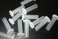
  • Flanged nylon shoulder spacers (McMaster Carr part 91145A154, shown in Figure 1)
  • PDMS compound (Dow Corning Sylgard 182 or 184)

Figure 1: Flanged nylon shoulder spacers for use as reservoirs

For optional gas pressure-driven flow:

  • Epoxy (Scotch-Weld DP-420)
  • Hose barb connectors (McMasterCarr part 51525K211)

Tools:

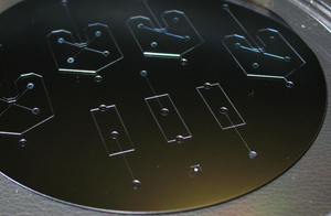
  • A mold for casting chips (Figure 2)
  • PDMS weighing and degassing equipment
  • A punching tool for creating ports in PDMS, such as thin-walled stainless hypodermic Tubing (Small Parts Inc., part HTX-22X or similar)
  • Tweezers
  • X-Acto knife

Figure 2: A microfabricated mold on a 4-inch silicon wafer

Procedure


1. Make a mold for your design, with reservoir locations 1 cm apart or more. This method was tested on SU-8 molds on silicon wafers, with resist thickness from 60 to 170 microns, without any special mold release treatment.

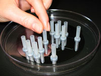
Pour a thin (~1 mm) layer of PDMS over the mold, and cure until solid. Place the nylon standoffs on top of the PDMS layer, over the ends of your channels, flange side down. Later you will punch to connect the reservoir with the channel on the underside of the chip. These reservoirs easily stay upright if the PDMS is still a bit sticky. (Figure 3)

Figure 3: Reservoirs are placed on a thin layer of PDMS cured over the mold

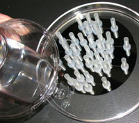
Figure 4: A second layer of PDMS holds the reservoirs in place

2. Pour a second 2 mm or thicker layer of PDMS around the reservoirs, covering the flanges to anchor them. (Figure 4) It doesn’t matter if PDMS seeps into some of the reservoirs. Let the PDMS level out, then cure until solid. The nylon reservoirs are OK at temperatures up to 80ºC.

3. Cut out individual devices with the X-Acto knife and peel off devices plus embedded reservoirs. It’s best to grip the devices at the PDMS using tweezers, rather than pulling on the reservoirs. (Figure 5)

Figure 5: Reservoirs and channels are removed from the mold together

4. Use the punching tool to create a port in each reservoir that connects to the microfluidic channel, making sure to remove a core of PDMS from each port. This can be done from the channel side (Figure 6) or from the reservoir side.

Figure 6: Punched ports connect reservoirs to channels

5. Bond the punched chips to a glass, PDMS or other substrate using plasma activation or other method of choice. Figure 7 is a side view of a bonded chip, showing anchored reservoirs and punched ports on a molded PDMS chip, attached to a blank PDMS slab on a glass slide.

Figure 7: Side view of a sealed chip showing sunken reservoirs and ports

6. (Optional, for gas pressure-driven flow) Use epoxy to attach hose-barb connectors to the tops of any reservoirs you want to pressurize. Gas can be provided to each reservoir using Tygon tubing. The 1/16″ hose barb to Luer connectors, and 1/16″ ID Tygon tubing are a good match to the size of these reservoirs. Gluing adjacent Luer connectors together can help strengthen the assembly when several gas connections are anticipated.

7. Fill reservoirs through the open tops or through the bonded-on hose barbs. Dispensing from a syringe with a long needle or a needle threaded into a small diameter piece of tubing helps prevent trapped air by filling from the bottom up. Figure 8 shows a filled chip with barbs for gas tubes.

8. While these reservoirs have been pressurized up to 30 psi before delaminating, they are easily removed from the chip by bending them sideways. Reservoirs can be peeled out of old chips for re-use if needed.

Figure 8: A filled chip ready for gas pressure-driven flow
Digg This
Reddit This
Stumble Now!
Share on Facebook
Bookmark this on Delicious
Share on LinkedIn
Bookmark this on Technorati
Post on Twitter
Google Buzz (aka. Google Reader)

Microfabrication design guidelines for glass micro- and nano-fluidic devices

Dave Hubera and Sumita Pennathurb
a Stanford Genome Technology Center, Stanford University, Stanford, CA, USA
b Department of Mechanical Engineering, University of California, Santa Barbara, CA, USA

Why is this useful?


Lab on a Chip devices fabricated with silicon dioxide or glass substrates represent the gold standard for many applications due to their robustness and repeatability.  However, fabricating these devices can be time consuming and expensive, particularly compared with devices created using rapid prototyping methods such as PDMS molding.  Therefore, in this edition of “chips and tips” we highlight a few of the issues that arise when designing and microfabricating fluidic devices and suggest tips that, we hope, will save you time, money, and perhaps another trip to the clean room.

1. Finding yourself – registration marks


Identifying a location in a channel with high precision can be very difficult, particularly when you are observing long stretches of otherwise featureless channels through high magnification objectives.  While this can be accomplished with expensive, high-resolution, motorized stages, it can also be accomplished elegantly using on-chip registration marks, such as rulers or other indicators.  Registration marks can be designed and fabricated with very little additional effort, by adding them to your channel mask design and subsequently etching the marks and fluidic channels in the same step.  But beware; if registration marks are too close to channels, minor lithography and etching errors can result in a poor seal and lead to leaks.  Recall that isotropic etching will produce channel (and mark) widths larger than the dimensions in the mask, so it is necessary to account for the final widths when positioning your marks relative to the channels.
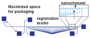
Figure 1: Schematic of a nanofluidic separation device with the following design considerations: 1) maximized space for packaging between the inlet holes, 2) on chip filters at the inlets, and 3) registration marks below the separation channel. In this particular design the registration marks are a separate, contiguous channel that can be filled with dye to aid in locating the adjacent separation channel (see Tip 5).

Ultimately, the selection of mark location relative to the channel is application dependent.  For greatest convenience, the marks and channels should appear within the same field of view on your microscope.  However, if your detection signal is very low, the presence of the marks may introduce additional noise (see tip 5).  In this case, it is preferable to locate your registration marks outside the field of view containing the channels.  Figure 1 shows a cross-channel design that includes tick marks underneath the separation channel.

2. Keeping it clean – on chip filters


All microfluidic chips eventually accumulate debris within the channel that can compromise performance or, worse, block the channel entirely.  Incorporating filters into your channel can help extend the working life of your devices.  These on-chip filters can be structures like pillars and, like registration marks, can be included in a design with little or no extra fabrication costs.  However, the design of the filter regions is critical if they are to successfully protect your channels without introducing other problems.  For example, when significant dead volumes are present, it becomes difficult and time-consuming to exchange samples or buffers because you must rely on diffusion to clear previous solutes from the dead volumes.  Figure 2 shows leakage of a fluorescent analyte from dead volumes at the corners of a square filter pad.  Here are some design considerations for on-chip filters:

  • Dead volumes arise when areas are not effectively flushed by fluid flow through the device. The filter shape should ensure that all regions experience approximately the same magnitude of fluid flow.  Also, sharp corners should be avoided. If necessary, lengths should be minimized to decrease the distance over which analytes must diffuse to escape the corner’s dead volume.
  • Large particles are excluded from the channel by the filter elements.  Consequently, filter elements should be sized to exclude the greatest number of particles.  However, the spacing between the elements should not be significantly smaller than the dimensions of the main channels or they can influence the behavior of the device.  For example, a spacing below 1 µm can result in concentration polarization effects due to the influence of the electric double layer.[1]
  • Small particles are trapped via adsorption to filter walls.  Trapping efficiency increases with the residence time of particles within the filter.  Thus, the filter area should be large relative to that of the channel.
  • The positioning of via holes may vary significantly, particularly if alignment of the channel and lid wafers is performed by eye (with no alignment tool) prior to bonding.  The design should allow for variation in the mating of the lid and the channel wafer, to ensure that filters are not bypassed by slightly misaligned via holes.

A simple on-chip filter schematic that minimizes dead volume is shown in Figure 2(b).  Many other designs are possible, and tradeoffs may be made between flow uniformity and areal expansion at the entrance to the filter.  Note, also, that filter designs can vary based on the design of the vias.
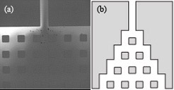
Figure 2: (a) Square on-chip filter design showing leakage of fluorescent dye from the corners of the filter. The dark region in the center indicates the region effectively flushed by fluid flow. In such designs, buffer or analyte exchange is extremely difficult due to dead volume in the corners. (b) A sample design that minimizes dead volume.

3. It’s not just the inside, the outside counts – fluidic interconnects


Many researchers have difficulty interfacing their microfluidic device with off-chip tubing, syringes, etc.  In a previous edition of Chips and Tips, the authors described a quick and cheap syringe tubing interface.[2]  Other solutions include commercially available options such as Labsmith[3] and Upchurch[4] fittings.  However, whichever interface you select, you must remember to allocate sufficient space for the connections on your device.  In general, these connectors are orders of magnitude larger than channel widths, and it is not uncommon to have channel lengths about the size of a fitting.  If a channel is too short, the fittings will overlap.  Even if they fit on the chip, the fittings may be so close as to interfere with their operation (e.g., loosening and tightening, adding or removing tubing) or with device function (e.g., introducing reflected light or autofluorescence into the detection region).  If the channel length must be on the order of the fitting size, we recommend that you design the ports such that you can maximize the space between them, for an example, see Figure 1.  Finally, be aware that the change in volume between the interconnect and the inlet of the microfluidic device may induce flow effects, such an nonlinear electrokinetic instabilities in the case of electroosmotic flow, and geometry induced vortices at sharp corners[5] – so be careful to design the channel to be long enough to neglect these (mostly harmful) hard-to-predict entrance effects in the main part of the channel.

4. Getting it together – bonding


Poor bonding between a channel wafer and its cover plate is a common cause of device failure.  It is particularly frustrating because bonding is the last significant fabrication step, after many hours have already been invested.  Many different bonding techniques (e.g., sacrificial bonding layers[6], spin-on glass[7-8], low temperature annealing with NaOH[9], and adhesive bonding[10]) have been developed; however, fusion bonding remains the most robust and reliable option for glass devices that can withstand the high temperatures required.  Therefore, we present a recipe (including a few tricks) to help achieve reliable fusion bonds between glass substrates:

  1. Before processing, ensure your substrates are sufficiently flat.  Inexpensive commercial glass wafers are often not flat enough to achieve a fusion bond.  If this is your only option, however, we recommend that you lap and polish the wafers prior to any processing.  Both the top and bottom substrate of the microfluidic chip must be lapped and polished.
  2. Clean and process your wafers.  Avoid processes that will roughen the bonding surface on the wafer because this reduces the surface area available for bonding and may lead to weakened substrates.
  3. After processing, thoroughly clean both top and bottom substrates using the following recipe.  Particulates or films will interfere with bonding. 20 minute clean in H2SO4 (90%) + H2O2 (10%) at 115º, 10 minute rinse with deionized (DI) water, spin rinse and dry (or dry very carefully by hand with clean nitrogen) .
  4. Hydrolyze the channel and cover wafers with a standard RCA1 clean, listed below, in order for the wafers to be completely clean and particulate free for the mating step. 10 minute clean in H2O (70%) + H2O2 (15%) + NH4OH (15%) at 80ºC, 10 minute rinse in DI water, spin rinse and dry (or dry very carefully by hand).
  5. Remove the native oxide that has formed on the wafers during processing with a short HF dip.  The etch should be sufficiently short to remove the oxide without etching the underlying channels. 20 second dip in 50:1 HF, 10 minute rinse with DI water, spin wash and dry (or dry very carefully by hand).
  6. Once the wafers are dry, position the channel wafer over the cover wafer such that your features align, then press the wafers together.  In a successful bond, you will see a wave of fringe patterns progress across the wafer, as the Van der Waals forces cause the wafer to pre-bond.  (It may be helpful to lightly bow one wafer by pressing on the center of one wafer, then releasing the wafer edge once contact is made in the center.)  These fringe patterns (or Newton rings) indicate the topology at the interface of the wafers and are only visible when the wafers are in intimate contact.  Particles will be surrounded by fringes (the number of fringes indicating the height of the particle).  In a perfect bond, all fringes will appear at the edge of the wafer.  If many particulates or fringes appear across the wafer, the bond will likely be poor, so separate the wafers and repeat steps 1-5.
  7. Place pre-bonded wafers in an oven (no vacuum needed, no weight needed) for 4-5 hours at the softening temperature of the material (500-600ºC for borofloat glass, 1100-1200ºC for quartz and fused silica).  We recommend ramping the temperature to the softening temperature, so as not to induce thermal stresses within the material.

5.  You’re special – special considerations for nanochannels


Nanochannels offer interesting new opportunities for studying nanoscale physics and performing fluidic operations on a scale less than that of a single cell; however, their size and the interfacial effects associated with their large (relative) surface areas introduce additional concerns.  Channel filling is a significant one and is generally accomplished via capillary action.  To do so, avoid introducing hydrophobic regions at the entrance of your channel (e.g., gold electrodes) and ensure your channels are not too long.  Of course, “too long” is dependent on your channel dimensions, for example, a 100 nm tall nanochannel longer than 50 cm will not fill successfully via wicking alone.  For long channels or adverse wicking conditions, you will need to apply pressure-driven flow.  The challenge with nanochannels is that their hydraulic resistance is large and high pressures are required to generate appreciable Poiseuille flow.  These pressures can easily be larger than those generated by syringe pumps (over 200 psi) and require high pressure fittings and interconnects.  Pressure filling in nanochannels can also introduce bubbles in the channel which are almost impossible to remove.

In nanoscale devices it can be challenging to locate the channels.  When channels are sufficiently wide, they can usually be seen under brightfield imaging, when channels are narrow (< 1µm) or nanofluidic chips are used for fluorescence measurements (i.e., in the dark), it is extremely difficult to find them, and the use of registration marks (see Tip 1) is critical.  When using registration marks with nanochannels, we recommend connecting the marks together into a parallel channel system with its own inlet and outlet.  The marks can be then be filled with fluorescent dye.  In this way, you can both locate the channel and also use the fluorescence intensity of the marks as a reference. However, keep in mind that the fluorescence from the channel may overwhelm the signal of a low concentration or dim analyte, so you may want to design the marks to be located just outside of the channel field of view.

References


[1] F. C. Leinweber, U. Tallarek, Langmuir, 2004, 20, 11637-11648.
[2] R.Martinez-Duarte and M. Madou, Quick and cheap syringe-tubing interfacing, Chips & Tips (Lab on a Chip), 26 June 2007.
[3] http://www.labsmith.com
[4] http://www.upchurch.com; A. Persat, T. Zangle, J. Posner and J. Santiago, On-chip electrophoresis devices: do’s, don’ts and dooms, Chips & Tips (Lab on a Chip), 26 March 2007.
[5] A. P. Sudarsan, V. M. Ugaz, Proc. Natl. Acad. Sci. U.S.A., 2006, 103, 7228-7233.
[6] A. Sayah, D. Solignac, T. Cueni and M. A. M. Gijs, Sens. Actuators, A, 2000, 84, 103-108.
[7] A. Satoh, Sens. Actuators, A, 1999, 72, 160.
[8] R. Puers amd  A. Cozma,  J. Micromech. Microeng., 1997, 7, 114.
[9] S. C. Jacobson, A. W. Moore, and J. Ramsey, Anal. Chem., 1995, 67 , 2059.
[10] Y. J. Pan and R. J. Yang, J. Micromech. Microeng., 2006, 16, 2666-2672.

Digg This
Reddit This
Stumble Now!
Share on Facebook
Bookmark this on Delicious
Share on LinkedIn
Bookmark this on Technorati
Post on Twitter
Google Buzz (aka. Google Reader)

Bonding Upchurch® NanoPorts to PDMS

Corey Koch, James Ingle, and Vincent Remcho
Department of Chemistry, Oregon State University, Corvallis, Oregon, USA

Why is this useful?


Upchurch (Oak Harbor, WA, USA) NanoPorts are one of the few commercial products on the market for making chip-to-world connections. NanoPorts are robust, easy to use, able to connect to standard tubing sizes (1/16-in OD and capillary tubing), and are particularly useful when connections are changed regularly. These fittings are constructed from polyetheretherketone (PEEK) and are intended to adhere to glass or silicon surfaces using epoxy or a heat-curable adhesive ring. The adhesive ring is compatible with many types of materials and NanoPorts have been used on a variety of polymers such as polycarbonate, cycloolefin (Zeonor), polyimide (Kapton), and polymethylmethacrylate.1-4 Unfortunately, NanoPorts do not readily adhere to one of the most common materials for prototyping microfluidic devices, polydimethylsiloxane (PDMS), and NanoPorts are often bonded to another material (commonly glass) in PDMS hybrid devices.5 A useful tip from Upchurch technical support is to imbed the NanoPorts into the PDMS chip during curing, but this can be cumbersome and PDMS only conformally seals to the PEEK surface so leakage can easily occur at the PDMS-PEEK interface. Fortunately, a tool common to the PDMS fab-lab, the oxygen plasma, can be used to bond PDMS to other substrates with the adhesive rings Upchurch supplies. Using an oxygen plasma to bond PDMS chips together using an adhesive tape has been mentioned in the literature,6 and this tip expands upon that work to form bonds between NanoPorts and PDMS using the supplied adhesive rings after exposing the PDMS surface to an oxygen plasma. It should be noted that the majority of this work was performed with the now unavailable acrylic-epoxy hybrid rings (3M Surface Bonding Tape 583), but the tip also works well with the new MEG-150 polyamide-epoxy resin adhesive ring.

What do I need?


  • Fully cured PDMS (Dow Corning Sylgard 184) microchip with via holes to microchannels
  • Upchurch NanoPort and supplied adhesive ring
  • Oxygen plasma or another source to oxidize the PDMS surface (simple methods based on corona discharge, peroxide, and a home-microwave have been presented in the literature)7,8,9
  • Clamp (try aluminum plates and a C-clamp or cantilever clamp)
  • A heat source (convection oven recommended)

What do I do?


1.  Prepare the PMDS microchip and NanoPort for bonding (Figure 1). Ensure the surfaces are fresh or clean with alcohol and air dry. If you are using the acrylic-epoxy hybrid adhesive ring, remove one side of the backing and stick it to the bottom of the NanoPort.

Figure 1.

2.  Oxidize the PDMS surface. This is commonly done in an oxygen plasma (Figure 2). Conditions vary, but based on experience and literature studies10,11 a pressure of 100 mTorr (oxygen gas), 20 W of RF power, and a 30 s exposure time provide an appropriate surface for bonding (ensure the surface is exposed to the plasma as in Figure 2).

Figure 2.

3. Quickly remove the PDMS from the plasma chamber and place the NanoPort with adhesive ring over the via hole to your microchannel (Figure 3). If you are using the new polyamide-epoxy resin adhesive ring, it is easier to place it on the oxidized PDMS surface using tweezers (because it is not tacky and won’t stick to the NanoPort bottom) and then set the NanoPort on top of it.

Figure 3.

4.  Clamp the NanoPort-adhesive-PDMS assembly and place it in an oven for the recommended curing time and temperature (see Upchurch technical notes and adhesive links, conditions vary based on the adhesives and temperatures used). For the acrylic-epoxy adhesive ring, a curing time of 2.5 hr at 100°C was used; for the polyamide-epoxy resin adhesive ring, a cure time of 1.5 hr at 165°C was used. Polycarbonate blocks (Figure 4) can be used for clamping at lower temperatures (< ~140°C); aluminum is suggested for higher temperatures.

Figure 4.

5. Your well-bonded NanoPort interconnect to PDMS is now ready to use! (Figures 5 and 6). In control experiments without plasma exposure, neither adhesive adhered to the PDMS and they fell off with minor stress. Testing the bond directly after contacting the ring to oxygen plasma-activated PDMS surface (before heat cure) demonstrates bonding to the PMDS surface but not to the PEEK NanoPort. Failure testing of a completely bonded NanoPort results in tearing of the PDMS with the ripped polymer remaining on the adhesive ring. Bonds formed with the acrylic epoxy hybrid ring consistently withstood pressures up to 24 psi and several bonds withstood pressures above 40 psi, making the interconnect robust at pressures in the range of PDMS material failure (30-50 psi).12

Figure 5.

Figure 6.

Acknowledgements


This material is based upon work supported by the National Science Foundation under Grant No. DGE-0549503. This research was also supported by a research grant from the U.S. Environmental Protection Agency sponsored Western Region Hazardous Substance Research Center under agreement R-828772. This work has not been reviewed by the agency, and no official endorsement should be inferred.

References


[1] A. Muck and A. Svato, Rapid Commun. Mass Spectrom., 2004, 18, 1459-1464.
[2] S. J. Hart, A. Terray, T. A. Leski, J. Arnold and R. Stroud, Anal. Chem., 2006, 78, 3221-3225.
[3] Y. Yang, J. Kameoka, T. Wachs, J. D. Henion and H. G. Craighead, Anal. Chem., 2004, 76, 2568-2574.
[4] R. Barrett, M. Faucon, J. Lopez, G. Cristobal, F. Destremaut, A. Dodge, P. Guillot, P. Laval, C. Masselon and J.-B. Salmon, Lab Chip, 2006, 6, 494-499.
[5] L. A. Legendre, J. M. Bienvenue, M. G. Roper, J. P. Ferrance and J. P. Landers, Anal. Chem., 2006, 78, 1444-1451.
[6] L. Xie, S. C. Chong, C. S. Premachandran, D. Pinjala and M. K. Iyer, Electronics Packaging Technology Conference, 2005, 93-97.
[7] K. Haubert, T. Drier and D. Beebe, Lab Chip, 2006, 6, 1548-1549.
[8] G. Sui, J. Wang, C. C. Lee, W. Lu, S. P. Lee, J. V. Leyton, A. M. Wu and H. R. Tseng, Anal. Chem., 2006, 78, 5543-5551.
[9] B. T. Ginn and O. Steinbock, Langmuir, 2003, 19, 8117-8118.
[10] S. Bhattacharya, A. Datta, J. M. Berg and S. Gangopadhyay, J. Microelectromech. Syst., 2005, 14, 590-597.
[11] B.-H. Jo, L. M. Van Lerberghe, K. M. Motsegood and D. J. Beebe, J. Microelectromech. Syst., 2000, 9, 76-81.
[12] J. C. McDonald, D. C. Duffy, J. R. Anderson, D. T. Chiu, H. Wu, O. J. A. Schueller and G. M. Whitesides, Electrophoresis, 2000, 21, 27-40.

Digg This
Reddit This
Stumble Now!
Share on Facebook
Bookmark this on Delicious
Share on LinkedIn
Bookmark this on Technorati
Post on Twitter
Google Buzz (aka. Google Reader)