Author Archive

Plug-and-play reservoirs for microfluidics

Christopher Y. Wong*, Georgian Ionut Ciobanu*, Mohammad A. Qasaimeh, and David Juncker
Micro and NanoBioEngineering Laboratory, Biomedical Engineering Department, Faculty of Medicine, McGill University, Montreal, Canada.
* Authors contributed equally

Why is this useful?


Microfluidic and lab-on-a-chip (LOC) devices are typically connected to external sample reservoirs. A significant issue for LOC devices is interfacing multiple sample reservoirs and connecting them both to external pressure controllers or syringe pumps and to the microfluidic chip [1,2]. Researchers typically use home-made reservoirs and interfacing them to the chip and the controllers requires specialized skills and training and/or additional fabrication steps.[3,4] Often the connections are unreliable and leaky, and as a consequence much time is lost in setting them up and it is difficult to add or remove connections from the reservoirs.

Here we introduce a “plug-and-play” reservoir that allows for multiple connections to be simply plugged in. The reservoirs are made using off-the-shelf threaded microcentrifuge tubes and screw-on septum caps. Needles, capillaries and steel tubing can be inserted one at a time – or in combination – through the cap’s septum and used to connect the reservoir to a pressure source and to one or several inlets of a microfluidic chip. The connectivity between reservoir and pressure source(s) and chip(s) can be adapted to specific needs, for example to form a reservoir with a single input and a single output, or with multiple inputs and outputs. Reservoirs with single or multiple input/output lines can be switched easily by by unscrewing the microcentrifuge tube and screwing the cap with the capillaries on another microcentrifuge tube containing a different solution.

The reservoirs are cheap, disposable, easy to assemble, and robust enough to support pressures up to 345 kPa (and even higher pressures with the variant described in the supplementary material) while having almost no dead volume. The connection of reservoirs to microfluidic chips – or to other reservoirs so as to form complex circuits – can be performed in a matter of seconds. Arrays of off-chip reservoirs can be assembled within racks and many lines can be connected at high density to a microfluidic chip. These plug-and-play reservoirs are a versatile solution to the world-to-chip interface and should find widespread application for microfluidic experimentation.

What do I need?


For the reservoir:

  • threaded screw cap with membrane/septum [5]
  • threaded microcentrifuge tube (any volume, as long as it has the same thread type as the cap) [5]

For the connections:

  • sharp hypodermic needle with Luer-Lock (any size from 23 to 16 gauge) [6]
  • 1/16″ ID Tygon tubing or other preferred tubing [7]
  • male Luer-lock to 1/16″ ID hose barbed tubing adapters [7]
  • glass capillary (Note: OD of glass capillary needs to be smaller than ID of needle) [8]

Optional for other connection types (shown in supplementary materials):

  • 0.0250″ OD hollow steel tubing [9]
  • 0.0200″ ID microbore Tygon Tubing [10]

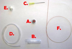
Fig. 1 shows the required parts. Fig. S1 in the supplementary materials shows the alternative options in our laboratory of microcentrifuge tube sizes and input/output connection types. (A) Threaded screw cap with membrane/septum [5]. (B) Threaded microcentrifuge tube [5]. (C) Sharp 20G1½ hypodermic needle with Luer-Lock [6]. (D) 1/16″ ID Tygon tubing [7]. (E) Male Luer-lock to 1/16″ ID hose barbed tubing adapter [7]. (F) Glass capillary of 350 µm OD [8].

Figure 1. Different parts used to make the reservoir.

What do I do?


1. In order to insert a glass capillary to serve as an output, use a sharp hypodermic needle with an inner diameter (ID) that is just larger than the capillary’s outer diameter (OD). Insert the needle into the membrane screw cap and then slide the capillary through the needle, as shown in Fig. 2.

Figure 2. Insert a needle into the membrane screw cap and pass the glass capillary through the needle.

2. Screw the cap onto a reservoir of the desired size and then remove the needle while holding the capillary in place, as shown in Fig.3. Repeat steps 1 & 2 for every additional glass capillary connection required.

Figure 3. Pulling the needle out but keeping the capillary in place fixed by the membrane.

3. Insert the input pressure needle to appropriate depth (see next section for details) and connect to the Tygon tubing to the needle using the Luer-lock to tubing adapters, as shown in Fig.4. Repeat this step for every additional Tygon tubing connection required.

Figure 4. Reservoir with a needle connection interfaced to a glass capillary (typically connected to the microfluidic chip) and Tygon tubing with a Luer-lock adaptor (typically connected to the pressure source) which can be used to control the flow from the reservoir to the chip.

4. The reservoir is completed. Unscrew the cap from the container and fill it with your reagent and screw the cap back on.

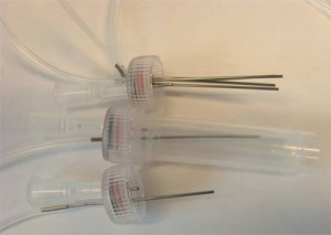
5. (Optional step) Instead of using a glass capillary, a steel tube connected to Tygon microbore tubing can be used. We used 0.0250″ OD steel tubing, inserted into 0.0200″ ID Tygon tubing and then forced the pin through the septum, as seen in Fig. 5. Multiple steel-Tygon tubing connections can be connected to one septum as shown in Fig. S2.

Figure 5. Steel tubing and Tygon microbore tubing connected to a reservoir.

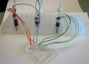
6. Connect the 1/16″ Tygon tubing to the pressure source and the capillary (or the microbore Tygon tubing) to the chip. Make sure to create slightly smaller sized holes for the input connections on the chip to create a tight seal. When using multiple reservoirs, they can be placed into microcentrifuge tube racks for easy handling (Microtube Storage Racks), as shown in Fig. 6.

Figure 6.  A picture of a chip connected to three reservoirs placed on a storage rack, each with an independent input line and multiple outputs.

7. Everything is now ready to use!

What else should I know?


This setup is simple, easy to build and can be done in less than a minute. Depending on the cap, the membrane/septum provides an airtight seal, but after inserting and removing needles more than a few times, especially with larger needles, leakage becomes apparent. Since the system is pressure controlled, a small leakage rate relative to the supply flow rate can be tolerated. Only a limited number of connections, up to 10 in our experience, can be connected to a single cap or else leakage becomes excessive. The reservoirs work well up to 345 kPa, and for higher pressure applications solid caps can be used as described in the supplementary material.

It is important to maintain the needle connected to the pressure source above the liquid surface in order to prevent the formation of bubbles. Be careful of the sharp points and remember to dispose of the needles properly.

Supplementary materials


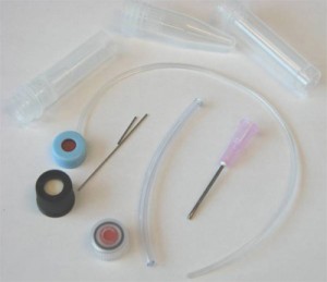
Figure S1. The different available options (excluding glass capillaries) in our laboratory of microcentrifuge tubes sizes, membrane caps, steel tubing, and input/output connections.

Figure S2. Multiple tubing outputs through multiple inserted steel tubing.

The presented setup above was not tested at pressures higher than 345 kPa, and at pressures above 140 kPa, there was minimal gas leakage. However, we have developed another setup that works without any leakage, even at 345 kPa, but requires several minutes to make and a precision micro-drill. This setup does not use a membrane cap, but a conventional screw cap without a membrane. Using suitable micro-sized drill bits, different sized holes can be made in the micro tube or the cap. After inserting the output capillaries or steel tubing and the input syringe needle, Instant Krazy glue [10] is applied to affix the inputs and outputs at the precise place. Dual melt glue [11] is then applied to seal the terminals from air/liquid leaks. The final setup is shown in Fig. S3.

We mention here that this setup is permanent and should be robust at high pressure applications. At the same time, it requires a precision micro drill, more time to make, and it is less flexible in the sense that it is harder to modify the interface.

Figure S3. High pressure off-chip containers with one Luer-Lock input and one glass capillary output at the bottom.

References


[1] S. Li and S. Chen, IEEE Trans. Adv. Packag., 2003, 26, 242-247.
[2] R. Lo and E. Meng, Sens. Actuators, B, 2008, 132, 531-539.
[3] T. Liu, E. V. Moiseeva and C. K. Harnett, Integrated reservoirs for PDMS microfluidic chips, Chips & Tips (Lab on a Chip), 22 April 2008.
[4] T. Das et al., Interfacing of microfluidic devices, Chips & Tips (Lab on a Chip), 27 February 2009.
[5] Sarstedt AG & Co.: http://www.sarstedt.com/
[6] BD: http://www.bd.com/
[7] McMaster-Carr Supply Company: http://www.mcmaster.com/
[8] Polymicro Technologies: http://www.polymicro.com/
[9] New England Small Tube: http://www.nesmalltube.com/
[10] Small Parts, Inc.: http://www.smallparts.com/
[11] Krazy Glue: http://www.krazyglue.com/
[12] The Stanley Works: http://www.stanleyworks.com/

Digg This
Reddit This
Stumble Now!
Share on Facebook
Bookmark this on Delicious
Share on LinkedIn
Bookmark this on Technorati
Post on Twitter
Google Buzz (aka. Google Reader)

A remote syringe for cells, beads and particle injection in microfluidic channels

Jean-Christophe Baret
Institut de Science et d’Ingénierie Supramoléculaires (ISIS),
Université de Strasbourg, CNRS UMR 7006, Strasbourg, France
jc.baret[at]unistra.fr

Why is this useful?


In suspension, cells, beads and particles tend to sediment at a speed given by the balance of viscous drag and gravity force. In classical biological experiments, the most straight-forward solution to keep cells in suspension is to shake large volumes. This type of system is relevant at high Reynolds number but is not very compatible with the classical systems used to inject small amounts of liquid in confined geometries, such as microfluidic systems.

Another common way to prevent sedimentation is to match the densities of the particles and the carrier fluid, or to increase the viscosity of the carrier fluid to increase sedimentation times. However, these solutions are not always suitable due to the biological or physical constraints of a microfluidic experiment. For example, increasing viscosities increases the pressure drop in microchannels, and additives for density matching are not always biocompatible.

Previously in the Chips and Tips section a system has been described for cell injection [1]. With a similar system, we observed that sedimentation along the tubing binding the syringe reservoir to the chip hinders good mixing of the cells. This tubing should therefore be as short as possible, which is sometimes incompatible with the large footprint of the syringe pumps or other equipment around the microfluidic chip. Interestingly, in another Chips and Tips section, a system for temperature control of syringe pumps has been described [2]. The idea there was to use a syringe pump to pump liquid in order to move the piston of another syringe placed in a temperature-controlled bath. This system still showed problems related to the length of the connection tubing to the chip.

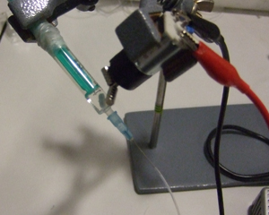
Here we combine both systems [1,2] to inject cells, beads and particles efficiently into microfluidic devices using small amounts of liquids (typically ~1 mL). The cells are initially placed in a syringe close to the chip and are automatically shaken inside the syringe using a small motor and a magnet. This syringe is then remotely actuated by another syringe mounted on a syringe pump [2] which reduces the footprint of the injection system in the vicinity of the chip. The tubing length from the syringe containing the cells to the chip can then be as small as 5 cm, which reduces the residence time of cells in the tubing and therefore reduces sedimentation.

What do I need?


  • Syringes: BBraun Injekt (2 mL or 5 mL)
  • Syringe needles: Terumo NEOPLUS 23G
  • Tubing: Fisher Scientific PTFE tubing (i.d. 0.56 mm, o.d. 1.07 mm)
  • Small magnets: Supermagnete, e.g. S-03-01-N
  • Teflon magnets: Fisher Scientific, length 6 mm, diameter 3 mm
  • Motor: Radiospares, e.g. 20GN steel 50:1 gear DC motor, 175rpm 12V
  • Power supply: Radiospares, e.g. LASCAR – PSU 130
  • Small equipment: stands and support, steel wire

What do I do?


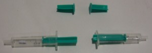
1) The first part of the procedure deals with preparing the syringes. This system is very close to the one presented in [1]. Cut the plungers of 2 syringes, and insert a magnet in one (Fig 1).

2) Bind them together with the metal wire (Fig 2).

Figure 1

Figure 2

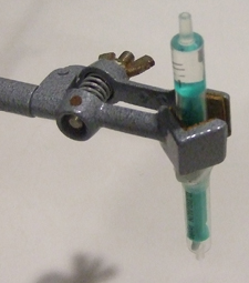
3) Fill the syringe that does not contain the magnet with water and hold it vertical (Fig 3).

Figure 3

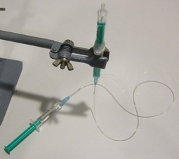
4) Insert the needles in the tubing, fill a third syringe with water, place the needle in position, flush the tubing with water and connect the syringe with the free needle (Fig 4). Make sure no air bubbles are present in the water phase: they will increase the response time of the system to flow rate modifications.

Figure 4

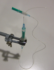
5) Invert the syringe to have the magnet in the upper part and fill this part with the liquid containing the cells, beads or particles (Fig 5) and connect a short needle with tubing (Fig 6).

Figure 5

Figure 6

6) Rotate the syringe and mount the motor with the magnets. Turn on the power supply (Fig 7). The speed of the motor is simply controlled by the voltage to guarantee gentle agitation of cells.

Figure 7

7) The system is now ready to be connected to a chip on one hand and to a syringe pump on the other (see video below). More sophisticated systems can probably be adapted to allow a temperature control of the syringe.

References


[1] R. Cooper and L. Lee, Preventing suspension settling during injection, Chips & Tips (Lab on a Chip), 21 August 2007.
[2] L. Capretto, S. Mazzitelli and C. Nastruzzi, An easy temperature control system for syringe pumps, Chips & Tips (Lab on a Chip), 22 April 2008.

Digg This
Reddit This
Stumble Now!
Share on Facebook
Bookmark this on Delicious
Share on LinkedIn
Bookmark this on Technorati
Post on Twitter
Google Buzz (aka. Google Reader)

How to prevent sagging during the bonding or lamination of chips with large aspect ratio chambers

Jie Xu and Daniel Attinger
Laboratory for Microscale Transport Phenomena, Department of Mechanical Engineering, Columbia University, New York, NY 10027, USA

Why is this useful?


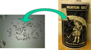
Assembling multiple layers by bonding or lamination is a simple way to manufacture complex multilayer microfluidic chips [1, 2].  However, bonding or lamination of chambers with large aspect ratio, i.e. wide and shallow, sometimes fails because of sagging. Figure 1 illustrates a sagging problem, which resulted in the top chamber wall being accidentally bonded to the bottom wall.  Here, we describe a tip to prevent sagging by using regular cooking salt.

Figure 1: Accidental bonding due to sagging

What do I need?


  • Cooking salt (grain size: normally 300 microns, can be further ground to less than 100 micron; melting temperature: 801 °C, good for lamination)
  • Precision tweezers
  • Stereomicroscope

What do I do?


1. Carefully pave the bottom of the chamber with ordinary salt as in Figure 2. Try to perform this action using fine tweezers under a stereomicroscope, if the chamber is too small.

Figure 2

2. Plasma bond or laminate the top layer. Be careful during handling, so that the salt does not end up in your DRIE machine.

Figure 3

3. After bonding is done, flush the microfluidic system with deionized water for several minutes to dissolve and remove salt particles. As figure 4 shows, the bonded chamber does not exhibit adhesion between the top and bottom wall.

Figure 4: No accidental bonding

References


1. J. Xu and D. Attinger, Drop on demand in a microfluidic chip, J. Micromech. Microeng., 2008, 18, 065020.

2. P. J. Hung, P. J. Lee, P. Sabounchi, N. Aghdam, R. Lin, and L. P. Lee, A novel high aspect ratio microfluidic design to provide a stable and uniform microenvironment for cell growth in a high throughput mammalian cell culture array, Lab Chip, 2005, 5, 44-48.

Digg This
Reddit This
Stumble Now!
Share on Facebook
Bookmark this on Delicious
Share on LinkedIn
Bookmark this on Technorati
Post on Twitter
Google Buzz (aka. Google Reader)

Quick assessment of the stability of flow generated by a syringe pump in a microfluidic device

Rachel Green and Siva A. Vanapalli
Department of Chemical Engineering, Texas Tech University, Lubbock, TX, USA

Why is this useful?


Syringe pumps are often used in a variety of microfluidic applications because of their portability and the ease with which flow rates can be changed. The syringe pump characteristics (type, age and wear), compliance in the tubing, a mismatch between the size of syringe used and the flow rate desired can generate pulsations in microfluidlic flows. These pulsations could be undesirable for lab-on-a-chip applications in which steady fluid flows are needed. The method described here is a quick means to assess the degree of pulsations present in flows driven by syringe pumps. The basic principle relies on using a microfluidic comparator [1,2] to detect small pressure fluctuations in fluid flows.

What do I need?


  • Microfluidic device with design as shown in Figure 2.
  • Ring stand
  • Ring stand clamp
  • Syringe pump
  • Distilled water
  • Dyed distilled water (refill ink)
  • Syringe (30 or 60 mL)
  • Tubing
  • Stereomicroscope

What do I do?


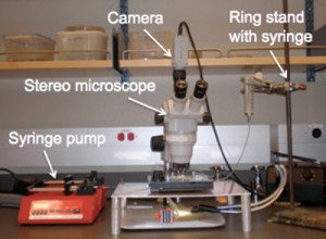
1. Set up ring stand with a wide-mouth syringe in the ring stand clamp (Figure 1). This is your hydrostatic head. The distilled water will go in this syringe.

Figure 1: Setup of the ring stand and syringe pump with the microfluidic device.

2. Place a syringe with the dyed distilled water into the syringe pump.

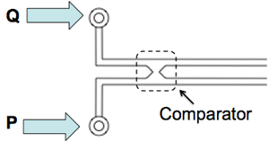
3. As shown in Figure 2, connect the syringe pump to the chip (labeled as flow rate Q). Connect the hydrostatic head, P, from the ring stand to the chip.

Figure 2: Microfluidic chip integrated with the comparator.

The outlets are open to atmospheric pressure. The device consists of two identical channels connected downstream to form a comparator region. At one inlet we impose a constant hydrostatic pressure (P) to generate steady flow and in the other inlet we use a syringe pump to introduce fluid admixed with a dye at a flow rate, Q.

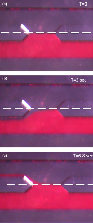
4. Start the syringe pump at the desired flow rate. Vary the height of the hydrostatic head until the two fluid flows meet at the symmetry line of the comparator (see the white line in Figure 3a).

5. Because the hydrodynamic resistances of the two channels are equal, if any pulsations are present in the syringe-pump driven flow then the dyed fluid will be displaced above or below the symmetry line (shown in white) in the comparator, as shown in Figure 3b and 3c.

Figure 3: Images of the fluid-fluid interface in the comparator at different times.

(a) The flows are steady and balanced. (b) After a time interval of 2 seconds, the dyed fluid is below the symmetry line indicating the syringe pump flow rate is lower than the flow rate corresponding to the imposed hydrostatic pressure. (c) After 6.8 seconds, the dyed fluid flow is above the symmetry line, indicating the syringe pump flow rate is greater than the flow rate corresponding to the imposed hydrostatic pressure.

What else should I know?


The method described is a quick assessment of the pulsations generated by syringe pump driven flow. For a more in depth study, we recommend using a precision hydrostatic head rather than a ring stand. We built a stand that can hold a syringe on a precision linear translation stage (Edmund Optics, Part # NT56-796). The stage allows the hydrostatic head to be adjusted at 0.1 mm intervals. Using this hydrostatic head and a video camera, one can precisely determine the number of fluctuations per unit time for a specified pump, flow rate, syringe size and tubing.

References


1. M. Abkarian, M. Faivre and H. A. Stone, Proc. Natl. Acad. Sci., 2006, 103, 538-542
2. S. A. Vanapalli, D. van den Ende, M. H. G. Duits and F. Mugele, Appl. Phys. Lett., 2007, 90, 114109

Digg This
Reddit This
Stumble Now!
Share on Facebook
Bookmark this on Delicious
Share on LinkedIn
Bookmark this on Technorati
Post on Twitter
Google Buzz (aka. Google Reader)

A method for rapid fabrication of microfluidic devices

Rajan Kumar, Robin L. Smith and Michael G. Pappas
Genome Data Systems, Inc., Hamilton, NJ 08610, USA

This Tip describes a useful variation on Holmes and Goddard’s method for rapid fabrication of microfluidic devices.[1]

Why is this useful?


Often, researchers need simple microfluidic devices with uniform height fabricated at short notice. Researchers also need to form channels to enclose materials deposited on glass surfaces, such as microarrays. A number of rapid prototyping methods are not compatible with these requirements. Holmes and Goddard have described an easy method for such preparing microfluidic flow systems.[1] We present a modification of this method using 3M double-sided permanent tape and heat curing with an inexpensive heat press. The resulting devices have a uniform height of ~80 micrometers. We have used such devices for microparticle assays and fluorescence microarrays in our laboratory.

What do I need?


  • Glass slide or other bottom plate substrate, e.g. plastic
  • Top plate substrate
  • 3M double-sided permanent tape 665 [2]
  • 3M double-sided removable tape 667
  • HobbyLite® T-shirt transfer press (Hix Corp., Pittsburg, KS)
  • Cutting board, razor blade, tweezers


What do I do?


1. Turn on the HobbyLite press and allow it to reach a temperature of about 100°F.

2. Draw the outline of the bottom plate (glass slide) on the cutting board. Draw the channel outline within the bottom plate outline.

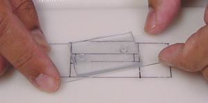
3. Attach the glass slide to the cutting board over the outline using a piece of removable, double-sided tape (Figure 1). This step prevents the glass slide from moving.

Figure 1

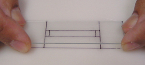
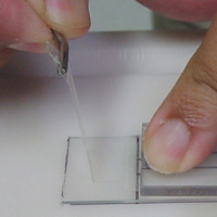
4. Attach a piece of double sided permanent tape to the top of the glass slide, covering the channel outline and leaving enough space on all sides of the channel for bonding (Figure 2).

Figure 2

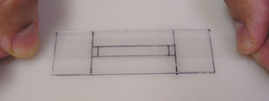
5. Cut out the double-sided tape from the channel outline using a sharp razor blade (Figure 3).

Figure 3

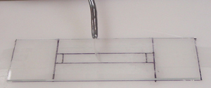
6. Lift one corner of the tape cut-out using the edge of the razor blade, then lift the tape cut-out with the tweezers (Figure 4).

Figure 4

7. Place the top plate on the slide, carefully aligning ports with the channel. Press down to ensure adhesion.

8. Cut excess double-sided permanent tape from each end of cover plate and remove with tweezers (Figure 5).

Figure 5

9. Gently twist and lift the glass slide off the cutting board (Figure 6).

Figure 6

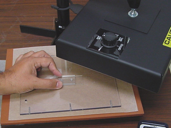
10. Place the assembly in the HobbyLite press and gently apply pressure for 5-10 minutes (Figure 7). Be careful not to apply too much pressure or glass materials may crack.

Figure 7

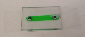
11. Remove the assembly from the press and allow it to cool to room temperature before use (~15 minutes). A completed device chamber filled with dye is shown in Figure 8.

Figure 8


Acknowledgements


This research is funded by an NIH grant GM078945 awarded to Genome Data Systems, Inc.

References


1.  R. J. Holmes and N. J. Goddard, Rapid prototyping of microfluidics, Chips & Tips (Lab on a Chip), 15 February 2007.
2. 3M Scotch® Double-Coated Tape 665 Permanent.

Digg This
Reddit This
Stumble Now!
Share on Facebook
Bookmark this on Delicious
Share on LinkedIn
Bookmark this on Technorati
Post on Twitter
Google Buzz (aka. Google Reader)

Simple and reversible bonding of glass to glass, quartz and sapphire wafers

Javier Atencia and Laurie E. Locascio
Biochemical Science Division, National Institute of Standards and Technology

Why is this useful?


We present a simple method to bond glass wafers reversibly by recreating the bonding that occurs occasionally among glass slides coming from a new box. Typically, the bond is clear without fringes, indicating that the wafers are in close contact, and the bond is so strong that it is impossible to separate the slides with bare hands, though it is not permanent; the slides can be separated with a razor blade.

This type of bonding is called “optical contact” or “direct-bonding”[1] (Isaac Newton was the first to observe it) and has been used extensively in the past, primarily in the optical field.[2] It has also recently been proposed for microfluidic chips using two polished glass wafers.[3]  Different protocols to induce optical bonding differ in the amount of labor and the bonding yield. The main advantages of this type of bonding include the following: the bond can be reversible; the method works with materials of different thermal expansion (it does not require heating); and the method does not require adhesive materials.

Here we introduce a simple, quick and reproducible realization of this type of bonding for microfluidic applications.

What do I need?


  • Two polished 3″ circular wafers (surface roughness <5Å ), one of them with etched patterns on one side (there are many protocols in the literature) and through holes to access the patterns. (For other wafer geometries see the final section of this Tip.)
  • A bath for piranha etching or RCA cleaning, and appropriate personal protective equipment.
  • Cassette for 3″ wafers and a spin-dryer for wafers (if one is not available, see the final section of this Tip), e.g. Semitool-101.
  • Two neodymium magnets.

What do I do?


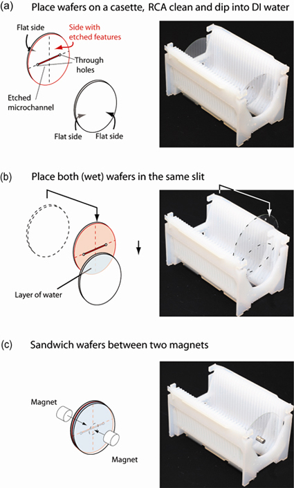
1. Place the glass wafers into different cassette slits (as usual), and place the cassette into the bath for RCA cleaning or Piranha cleaning (typically for 10 min.), Fig. 1(a).

2. Remove the cassette from the cleaning bath and place it in a bath of deionized water (for approx. 10 min.).

3. Remove the cassette from the deionized water bath, take one of the wafers out of its slit and place it into the same slit as the other wafer, taking care that the side of the wafer with the etched channels faces the other wafer.  The two glass wafers should attach to each other by capillary forces and have a thin layer of water in between, Fig. 1(b). Care should be taken not to touch the sides of the wafers that will be in contact.

4. Carefully place two strong magnets on either side of the wafers that are in contact, thus sandwiching the wafers, Fig. 1(c). The magnets should be centered on the wafers.

5. Run the automatic protocol for spin-drying the wafers. The centrifugal force removes the liquid layer between the wafers, bringing them into close contact.

6. Remove the bonded wafers from the spin-dryer and remove the magnets.  The microfluidic device is ready for use. (If the device will be used several hours later it is best to leave the magnets on the device until use.)

Figure 1. Preparation of glass wafers before spin-drying.

What else should I know?


Gas bubbles. Sometimes small gas bubbles may remain between the glass wafers after spinning. These bubbles can usually be removed by pressing on the glass wafers with your gloved fingers and driving them to the edges.

Reversible bond. If there are impurities such as small particulates between the wafers, the device will not bond well.  In this case, a razor blade can be used to separate the wafers. Clean the wafers again and repeat the operation.

Bonding Strength. We tested this bonding method using glass microchannels (500 micrometers wide) with a lid made of glass (borofloat), and found that it withstood pressures of 207 kPa (30 PSI) consistently without rupture 24 h after spinning.  We also tested a glass-sapphire and a glass-quartz bond and found that both consistently withstood pressures of 138 kPa (15 PSI).

Repeatability. We have used a device for months with this bonding without failure. We have also repeatedly separated the wafers with a razor blade, cleaned them, and bonded them again successfully for reuse.

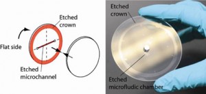
Surface quality. For this method to be successful, it is critical that the surface roughness is less than 5Å. If the wafers are not flat at the edges, etching a “crown” around the edges while etching the microchannels ensures proper bonding, see Fig. 2.

Figure 2. Example of etched crown to eliminate defects at the edges that prevent bonding.

Aspect ratio of etched features. Because there is no thermal bonding, high aspect ratio devices can be fabricated without collapse of the features. For example, we created a circular chamber 500 nm deep and 1.5 mm in diameter, without collapse.

Temperature. We have used these devices at room temperature only, and expect them to fail if higher temperatures are employed due to thermal stresses – particularly when the device is made of two different materials.
No spin-dryer system or different wafer geometries

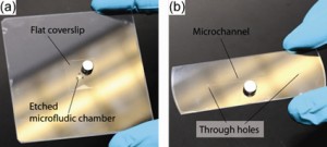
If a spin-dryer is not available, or if the wafers are different from each other or are not circular (see examples in Fig. 3), the same protocol can be used without spinning. However, in this case one should wait at least 24 h before using the device to allow the layer of water between the wafers to dry.

Figure 3. Bonding between flat glass pieces of non-circular geometries.

Acknowledgements


We are thankful to G. Cooksey for the photographs displayed in the figures.

Part of this work was performed at the NIST Center for Nanoscale Science and Technology Nanofab, which is partially sponsored by the NIST Office of Microelectronics.

References


[1] J. Haisma, N. Hattu, J. T. C. M. Pulles, E. Steding and J. C. G. Vervest, Appl. Opt., 2007, 46 , 6793-6803.

[2] V. Greco, F. Marchesini and G. Molesini, J. Opt. A: Pure Appl. Opt., 2001, 3, 85-88.

[3] Z. J. Jia, Q. Fang and Z. L. Fang, Anal. Chem., 2004, 76, 5597-5602.

Digg This
Reddit This
Stumble Now!
Share on Facebook
Bookmark this on Delicious
Share on LinkedIn
Bookmark this on Technorati
Post on Twitter
Google Buzz (aka. Google Reader)

An inexpensive and durable epoxy mould for PDMS

André Estévez-Torres, Ayako Yamada and Li Wang
Department of Chemistry, Ecole Normale Superieure, Paris, France.

Why is this useful?


To create microfluidic patterns on PDMS one usually pours PDMS on a mould composed of microfabricated resist features on top of a Si or glass wafer. However, these resist moulds are fragile and usually break after a few uses, making it necessary to perform microfabrication again. Transferring the microfabricated features to an epoxy mould conserves the resolution down to 1 µm[1] and allows: i) multiple and inexpensive copies of the mould, ii) hundreds of uses without significant ageing, iii) easy incorporation of macroreservoirs to the PDMS device without needing to punch them every time, and iv) isopropanol cleaning, which is not possible with AZ resists.

What do I need?


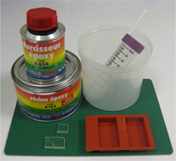
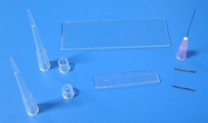
    Figure 1. Materials

  • Resist mould
  • PDMS
  • Silicone cake mould (e.g. SF025 financiers) from Silikomart (Mellaredo di Pianiga, Italy)
  • Epoxy resin (type R123, Bisphenol A/F epoxy resin) and hardener (type R614) from Soloplast-Vosschemie (Saint Egreve, France) or EasyCast Clear Casting Epoxy from Castin’Craft, Environmental Technology[2]
  • Trichloromethylsilane
  • Plasma cleaner

How do I do it?


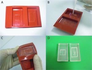
Figure 2. A) PDMS masters on the bottom of silicone cake molds. B) Pouring epoxy over PDMS masters. C) Peeling the epoxy+PDMS brick off the cake mold. D) Resulting epoxy molds.

1. Pour PDMS on the resist mould and cure it as you usually do.
2. Peel off the PDMS layer from the resist mould. Punch the macroscopic reservoirs if you need them. This PDMS part will be called PDMS master.
3. Put the PDMS master (microfabricated features on top) on the bottom of the silikomart cake mould. You may clean it with 3M tape.
4. Prepare the epoxy mixture as recommended by the manufacturer and remove the bubbles by vacuum pumping or ultrasonication.
5. Pour the epoxy mixture on the cake mould containing the PDMS master until you cover it with 2-3 mm of epoxy. Be careful to avoid making bubbles. If you are moulding small features you probably need to remove bubbles by vacuum pumping.
6. Wait for 24h at room temperature.
7. Remove the epoxy+PDMS brick from the mould and then peel off the PDMS master from the epoxy using a scalpel and tweezers. It peels off very easily.
8. The epoxy mould may be a little soft at this stage. Bake it in an oven at 70°C for one day – it becomes softer – and let it harden at room temperature for another day.
9. Silanize the epoxy mould by keeping it in a closed petri dish with a trichloromethylsilane-saturated atmosphere for 5 min. The first time you use the epoxy mould to make a PDMS device you need to put it into a plasma cleaner before silanization.
10. Pour PDMS on the epoxy mould as you usually do with other moulds. Cure it in the oven following your favourite recipe and peel it off. The first peel off needs to be performed slowly and carefully. Subsequent peelings off are straightforward.

Figure. 3. Optical microscopy image of A) PDMS master, B) epoxy mold and C) PDMS molded on epoxy. The images are 300 µm wide and the smallest feature is 10 µm.

References


[1] This type of technique, called replica moulding, has been reported to yield features down to 100-50 nm (Y. Xia et al., Replica moulding using polymeric materials: A practical step toward nanomanufacturing, Adv. Mater., 1997, 9, 147-149).
[2] http://www.eti-usa.com

Digg This
Reddit This
Stumble Now!
Share on Facebook
Bookmark this on Delicious
Share on LinkedIn
Bookmark this on Technorati
Post on Twitter
Google Buzz (aka. Google Reader)

Interfacing of microfluidic devices

Tamal Das
Department of Biotechnology, IIT Kharagpur-721302, India

Debapriya Chakraborty, Suman Chakraborty*
Department of Mechanical Engineering, IIT Kharagpur-721302, India
* e-mail: suman[at]mech.iitkgp.ernet.in

Why is this useful?


The integration of PDMS chips, with pumps or connections to reservoirs, has been found to pose serious difficulties because of its associated problems in leaking, interfacing with tubing, etc. Here, we present a simple approach for making reservoirs and also connecting devices with tubing for interfacing with pumps, without the aid of commercially available connectors and using commonly available consumables in the laboratory.

The PDMS mould is bonded with glass in two ways – using hydrophilic and hydrophobic means. Hydrophilic bonding involves using a plasma cleaner for oxidation. Hydrophobic bonding is done using a PDMS mixture. Here, we report easy and cost effective hydrophilic and hydrophobic bonding protocols. For example, the hydrophilic bonding can also be done without the use of conventional plasma oxidation.

What do I need?


  • PDMS base and curing agent (SYLGARD 184 silicone elastomer kit) in 10:1 wt/wt ratio
  • micropipette tip (2-200 µl pipette tips)
  • 20 gauge (outer diameter) needles
  • tubing (20 gauge inner diameter)
  • Piranha solution (H2O2 and H2SO4 solution in 1:1 vol/vol ratio)

Figure 1

What do I do?


1. Cut the syringe needles to the desired length (approximately 1.5 cm), preferably using wire electrical discharge machining. Any other needle cutter can be used if it can cut sharply the ends of the needles.

2. Punch holes in the PDMS mould using these needles at the inlet/outlet.

3. Bonding the PDMS mould to the substrate (Figure 2):

  • Hydrophilic bond:
  1. Oxidize the glass slide and the PDMS mould in freshly prepared Piranha solution.
  2. Dip the glass slide in the solution for 5 mins, and the PDMS mould for 10 secs. Dipping the PDMS mould for larger times may lead to damage to the mould because of strong oxidation
  3. Rinse them in deionised water at least three times. This step is required to remove any residual acid as well as to prevent hydrophobic recovery.
  4. Dry both the glass slide and the mould using a compressed stream of dry nitrogen gas.
  5. Place the mould over the glass slide and heat it at 70°C for 30 minutes.
  • Hydrophobic bond:
  1. Coat the glass slide with a thin layer (~ 10 µm thickness) of PDMS mixture (preferably by spin coater).
  2. Heat it at 70°C for 7 mins (this makes the PDMS hardened but still sticky)
  3. Place the PDMS mould on the sticky PDMS surface. In order to avoid wrinkles and air gaps, lay the mould down from one end to the other.
  4. Heat it for at least 30 mins at 70°C.

Figure 2

4. After bonding the PDMS mould to the glass, place the needles in the holes. Apply a small amount of PDMS mixture to the cylindrical surface of the needles. The PDMS mixture slowly settles down near the junction. Applying larger quantities of PDMS mixture may lead to seepage into the channel through the junction. Heat it immediately for 10-15 mins at 70°C. (Figure 3)

Figure 3

5. Cut a small piece of micropipette tip with at least one planar surface. Put a bit of PDMS mixture around the periphery of the planar surface. Place it centering the needles and heat it for 20 mins at 70°C. This makes the reservoirs. (Figure 4)

Figure 4

6. Pour PDMS mixture into the reservoirs around the syringe needle tips and heat it at 70°C for 25-30 mins until the supports become rigid. This provides the support for the needles. (Figure 5)

Figure 5

The tubing can be connected to these cut out needles, and the other ends connected to a syringe or peristaltic pump (Figure 6). If the connection to the pump is not desired and only the reservoirs are required then steps (1, 4, 6) are not required.

Figure 6

Digg This
Reddit This
Stumble Now!
Share on Facebook
Bookmark this on Delicious
Share on LinkedIn
Bookmark this on Technorati
Post on Twitter
Google Buzz (aka. Google Reader)

Overcoming interfacing issues by adding fumed silica

Alexander Iles
Dept. Chemistry, University of Hull, Cottingham Rd, Hull, HU6 7RX, UK

Problem


In microfluidics it is often necessary to interface chips using capillaries or plastic tubing. This can introduce a number of problems. For example, with glass chips it is rarely the case that the tubing or capillary is a perfect match for the reservoir hole that has been drilled into the device. Hence when using adhesives to attach tubing, the glue can seep down into the microdevice and clog its channels. Alternatively, with PDMS it is difficult to find anything that will stick to it and also securely hold a connecting tube in place. Nanoports can be used to interface devices, but they are expensive [1]. Small pieces of PDMS can be plasma bonded to a chip to create ports [2], but this involves extra fabrication steps and a plasma oven.
The solution:

To use fumed silica to create thixotropic adhesives. Adding fumed silica to epoxy resins or to PDMS creates adhesives that are extremely viscous and will not flow. Hence it can be added to epoxy resins to prevent seepage between access holes and tubing with glass chips and also it can be added to PDMS to make highly effective ports for PDMS chips.

Materials


  • A small quantity of premixed epoxy resin or PDMS
  • Fumed silica. Fumed silica is manufactured by Degussa and can be obtained as a free sample by visiting their website[3]
  • A container and a spatula for mixing

Procedure


1. Take a small quantity of your resin of choice (epoxy or PDMS). Place this in your mixing container.

2. To the resin, add a small amount of fumed silica, and using a spatula, mix it into the resin. A good starting point is 1 part fumed silica to 11 parts pre-mixed PDMS (by weight). Warning! Always wear a dust mask when handling fumed silica, it is like very fine dust. One sneeze and it will go everywhere! Bear in mind the working life of your epoxy resin, some resins set in 5 minutes or less, which will not give much time for mixing in fumed silica.

3. Once the fumed silica has been incorporated into the resin, add more as necessary to obtain the required thixotropy. Then it is ready for application.

4. For glass chips, always wipe down the surface of the device with acetone and allow it to evaporate before applying epoxy, to ensure a good bond.

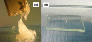
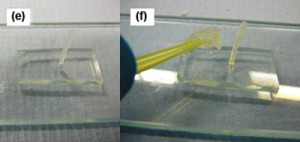
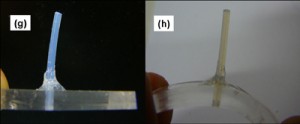
5. Place the tube or capillary into the hole. Use a pipette tip or small applicator to apply a small blob of adhesive around the interface. The resin mixture will not flow, so it will be necessary to smooth it around the tube or capillary with the applicator. The procedure is similar for PDMS devices, except that a hole must first be bored into the chip, the tube inserted and then the thixotropic PDMS applied. In both cases, cure times can be reduced and adhesion strengths improved if an oven at 60-70 ºC is used for curing. Refer to Figures 1 and 2 for step by step photographic explanations and further details.

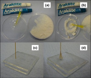
Figure 1. Procedure for making thixotropic epoxy for interfacing glass chips: (a) Mix the epoxy in a suitable container and have some fumed silica ready for use. (b) Add the fumed silica and mix in. (c) Insert a capillary or tube into a hole on the glass chip, after wiping it with acetone. (d) Apply thixotropic epoxy to the interface between the chip and the connector and leave to cure.

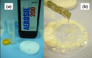
Figure 2. Procedure for making thixotropic PDMS for interfacing PDMS chips: (a) Mix the PDMS in a suitable container and have some fumed silica ready for use. (b) Add the fumed silica and mix in. (c) The PDMS should now look like this. (d) Cut a hole using a boring tool in your PDMS chip. (e) Insert a tube (e.g. PTFE) of a suitable size into the hole on the PDMS chip. (f) Apply thixotropic PDMS to the interface between the chip and the connector tube. (g) Leave it to cure, either at room temperature or at 60-70 ºC. (h) The completed interface. A silica capillary from, for example, a syringe pump, can now be securely inserted into the PTFE tubing and removed again as often as required without leaking. The PTFE tubing has an I.D. of 300 µm, which makes a good interference fit with standard 375 µm O.D. silica capillaries.

Conclusion


Adding fumed silica to PDMS or epoxy resins allows the researcher to fine tune the viscosity of their system as desired. Thixotropic PDMS is probably one of the best materials for interfacing PDMS devices, since few things will stick better to PDMS than PDMS itself!

References


[1] C. Koch, J. Ingle, and V. Remcho,  Bonding Upchurch® NanoPorts to PDMS, Chips & Tips (Lab on a Chip), 12 February 2008.

[2]  S. Mohanty, D. J. Beebe and G. Mensing, PDMS connectors for macro to microfluidic interfacing, Chips & Tips (Lab on a Chip), 23 October 2006.

[3] http://www.aerosil.com/aerosil/en/default

Digg This
Reddit This
Stumble Now!
Share on Facebook
Bookmark this on Delicious
Share on LinkedIn
Bookmark this on Technorati
Post on Twitter
Google Buzz (aka. Google Reader)

Profile measurement for microstructures made in hard material

Jie Xu and Daniel Attinger
Laboratory for Microscale Transport Phenomena, Department of Mechanical Engineering, Columbia University, New York, NY 10027, USA

Why is this useful?


Precise cross-section measurements are very important for microfluidic structures, such as micro-channels, chambers, pillars. However the manufacturing process can be imprecise in terms of channel depth (soft lithography, micro-milling) or channel width (micro-milling). A profilometer can be used after manufacturing, but the maximum depth is usually limited and the tip cannot probe channels thinner than 5 microns. Therefore, we present a way to easily measure the cross-section of microstructures made in hard material, such as SU-8, PMMA and silicon, in a large range of sizes.

What do I need?


  • PDMS and its fabrication equipment, e.g. vacuum pump, heater and aluminium foil
  • Razor blade
  • Microscope

What do I do?


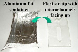
1. Put your chip with microstructures facing up in an aluminium foil container [1].

Figure 1

2. Pour a 2-3mm thick PDMS layer on top of the chip and cure it. A vacuum might be needed to remove the bubbles in the PDMS, if your features are small.

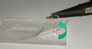
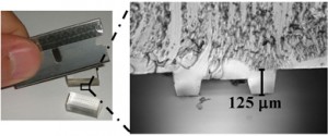
3. Peel off the PDMS and cut it at the location of your interest. Try to perform the cut under a stereomicroscope, if you feel it hard to locate your razor blade precisely.

Figure 2

4. Use the microscope to visualize the cross-section of the cut PDMS, and all the dimensions can be measured from the image.

Figure 3

References


[1] A. O’Neill, J. Soo Hoo and G. Walker, Rapid curing of PDMS for microfluidic applications, Chips & Tips (Lab on a Chip), 23 October 2006.

Digg This
Reddit This
Stumble Now!
Share on Facebook
Bookmark this on Delicious
Share on LinkedIn
Bookmark this on Technorati
Post on Twitter
Google Buzz (aka. Google Reader)