Gabriele Pitingolo1, Valerie Taly1 and Claudio Nastruzzi2
1INSERM UMR-S1147, CNRS SNC5014; Paris Descartes University, Paris, France. Equipe labellisée Ligue Nationale contre le cancer.
2Dipartimento di Scienze della Vita e Biotecnologie, Università di Ferrara, Ferrara, Italia
*Email: gabriele.pitingolo@parisdescartes.fr, nas@unife.it
Why is this useful?
It is well known that the rapid proliferation of information and communications technologies (ICT) has resulted in a global mountain of high-tech trash (e-waste). The problem with e-waste is not only the accumulation of electronic products and therefore the high disposal costs, but rather the hazardous substances present in their various components. Therefore, the importance of recycling is evident in the area of resource and energy conservation, finding a new, second life for electronic components.
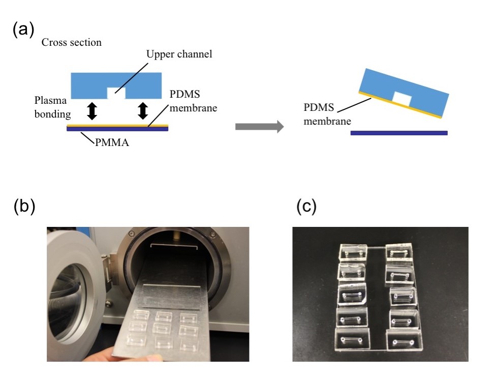
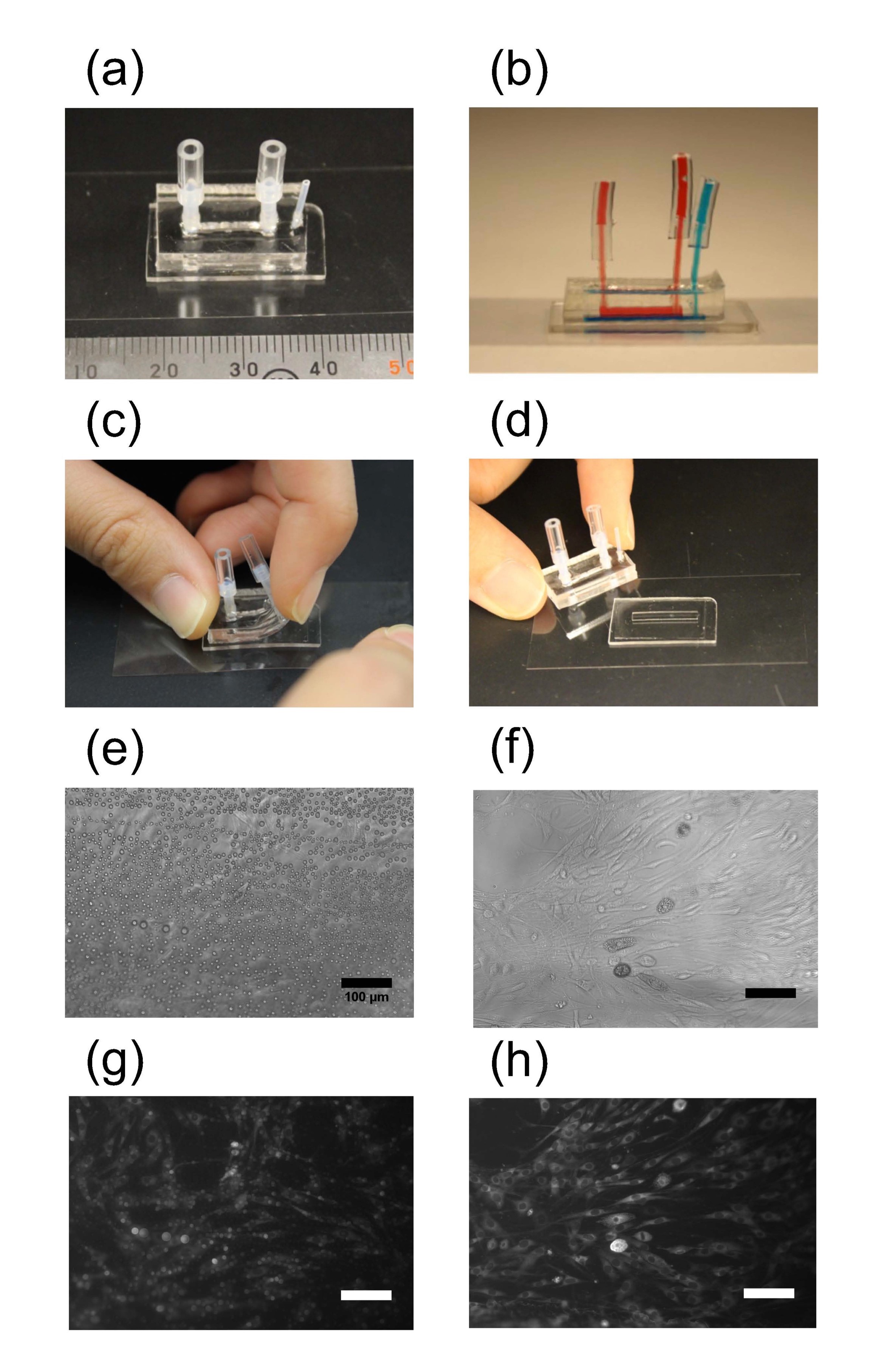
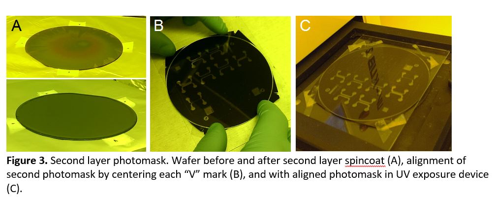
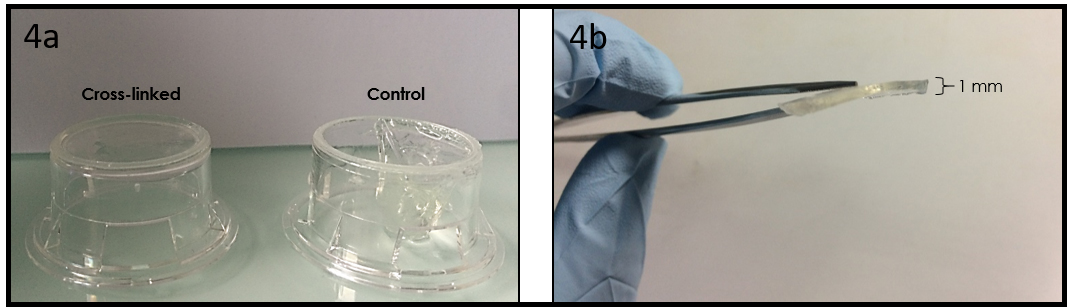
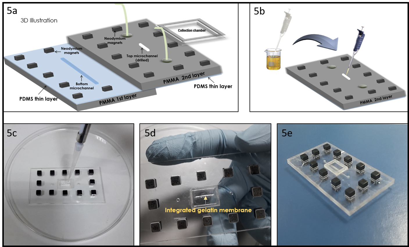
Spin coaters are widely used instruments useful to deposit uniform thin films to flat substrates [1]. In microfluidics, the spin coating is used to coat a photoresist layer (such as SU-8) or to bond separate substrates by using the adhesive properties of PDMS. The spin coating technology is also used to fabricate thin polymer membranes. PDMS membranes are, for example, employed for a wide range of applications due to their several advantages. For instance, being PDMS membrane permeable, they can be used to exchange gas (in cell culture application for example) or small molecule (in filtration application) [2]. In addition, as recently reported, spin coating is suitable to fabricate microchannels with a circular section [3].
Unfortunately, most commercial spin coaters are expensive (£2,000-6,000) and possess some unwanted or redundant specifications, not necessarily needed for the fabrication/modification of microfluidic devices.
In this respect, we present here a tip to develop portable spin coaters by recycling computer fans and mobile phone wall chargers. The most common fans in personal computers have a size of 80 mm, but the size can range from 40 to 230 mm. It’s also known that the fans of different size show also a different rotational speed. Typically, the 80 mm fans have a rotational speed of 2000 rpm (that represent a suitable speed for common thin layering in microfluidics).
What do I need?
Parts for the spin coater
- Personal computer fan
- Insulated male/female wire pin connectors
- Tesa power strip
- Wall chargers from (old) mobile phones
Parts and chemicals for the specific examples
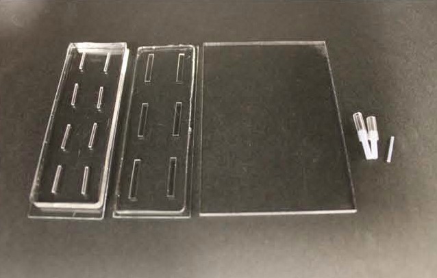
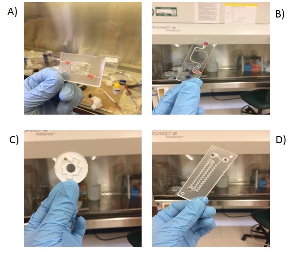
- Milled poly(methyl methacrylate) (PMMA) microchannel
- Glass slide
- Sylgard® 184 silicone elastomer kit
- Clumps
What do I do?
Assembling of spin coater
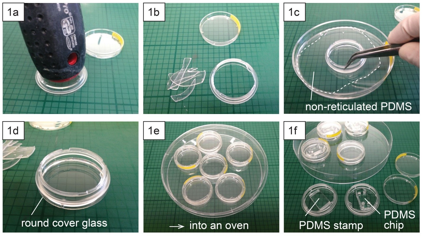
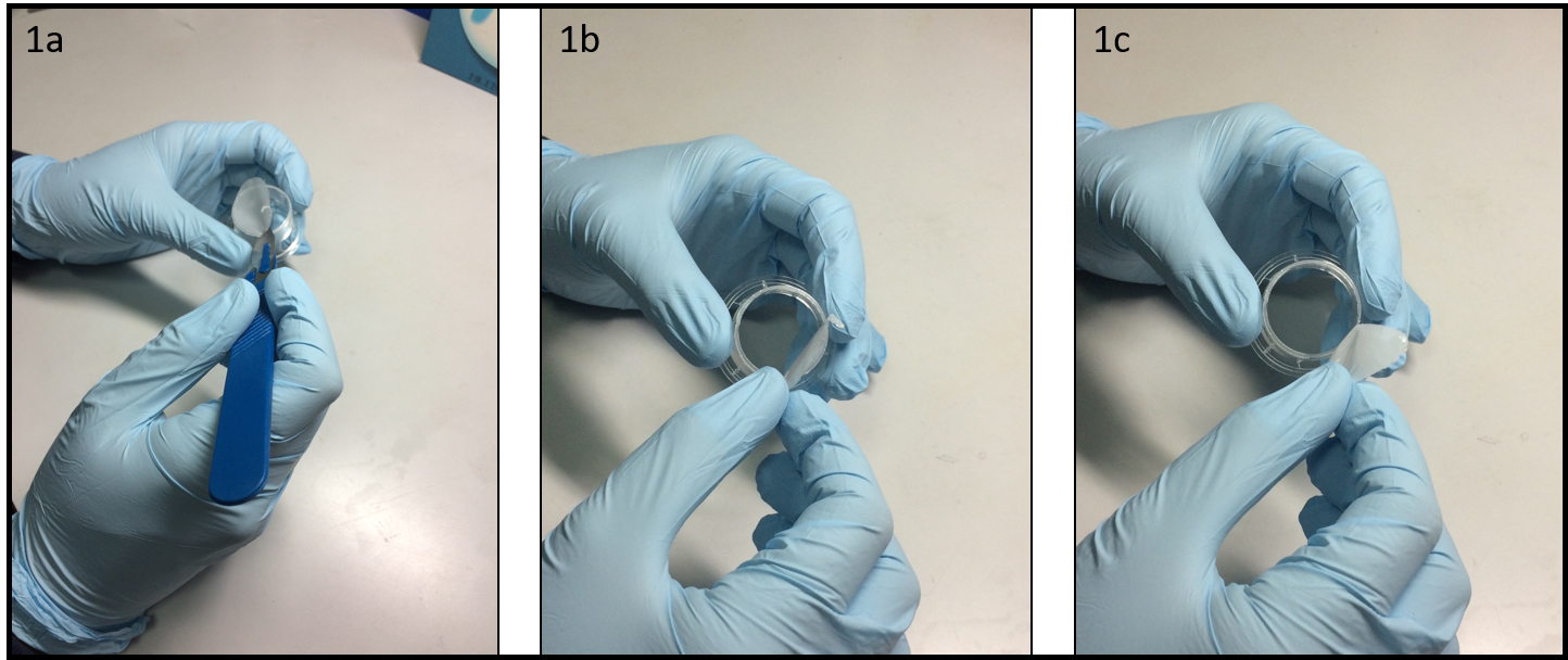
1.Remove the fan from an old pc (or mac, if are particularly posh) (Fig.1).
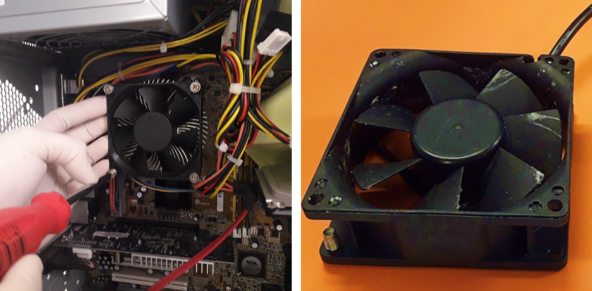
2. Connect the wall charger and the fan wires with insulated female and male wire pins. Afterwards, to turn on the fan, connect the female and male pins.

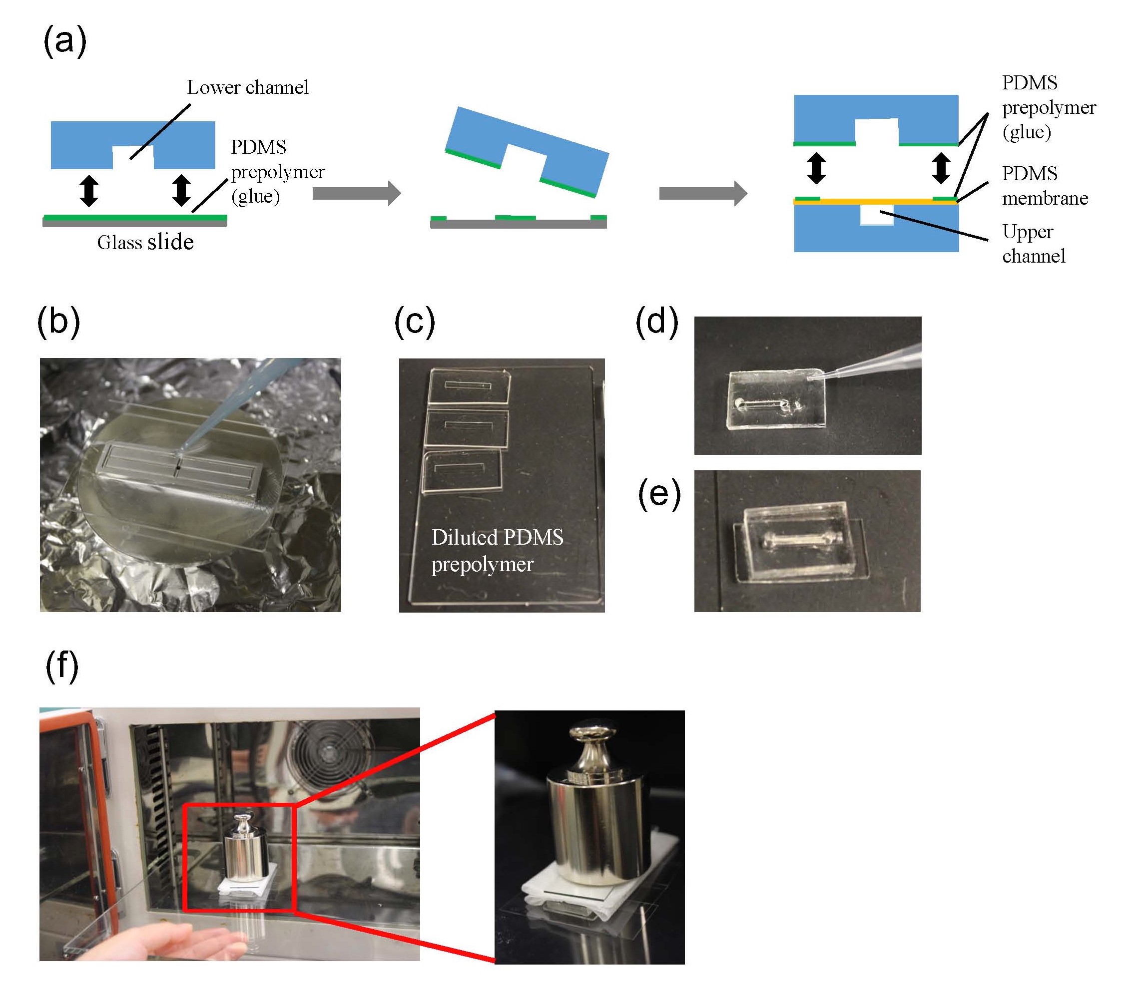
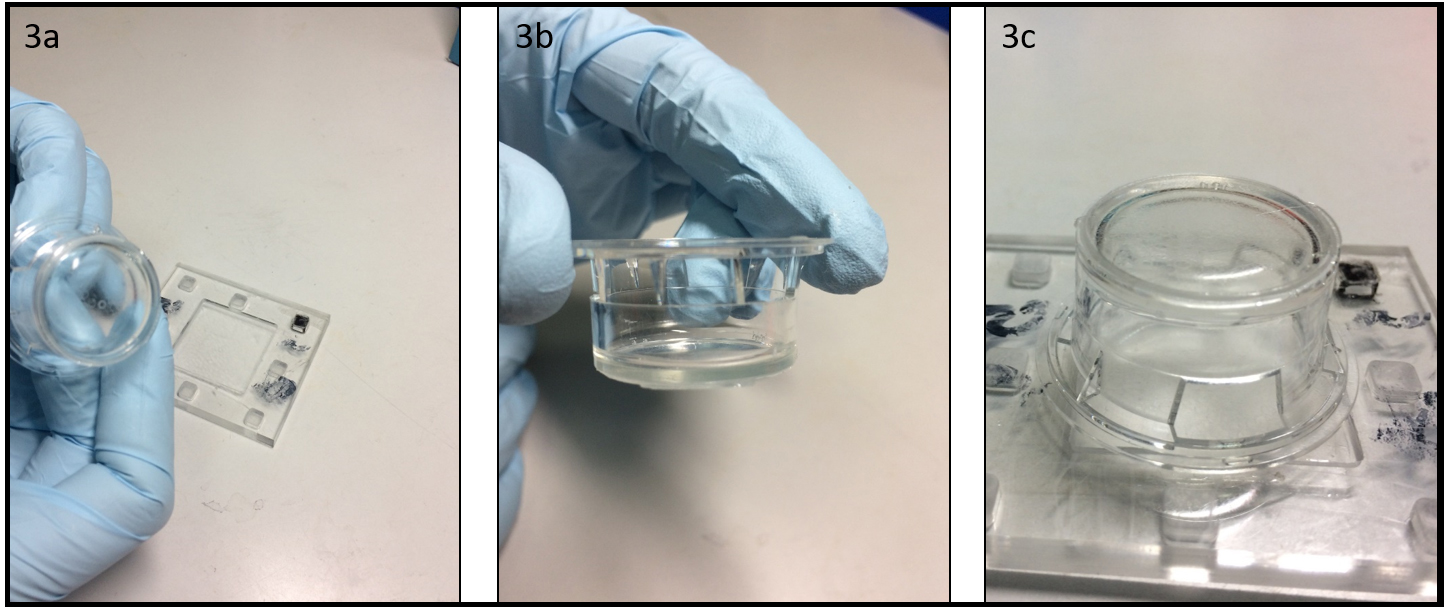
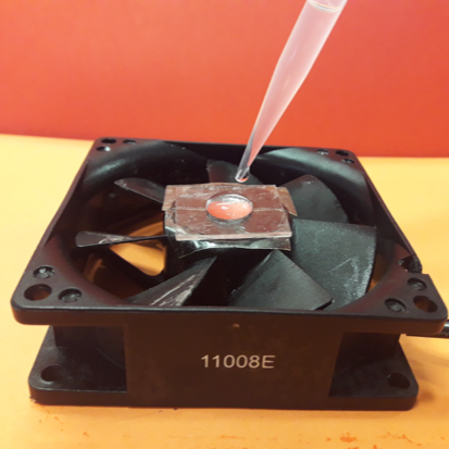
3. Using the tesa power strips, secure the substrate (i.e. glass slide or PMMA microchannel) to the central part of the fan (left picture). For devices larger than the fan, use an adeguate plastic stopper to elevate the device (right picture).

4. Drip, by a (micro)pipette, the liquid containing the coating material on top of the substrate.
5. Turn on the fan and spin coat the substrate for about 30 seconds (time can vary depending on the substrate viscosity and coating thickness required).
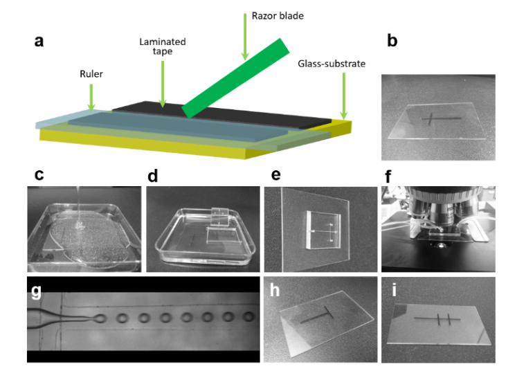
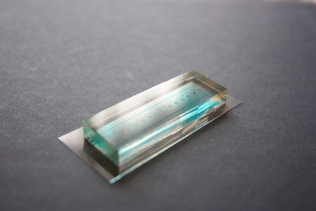
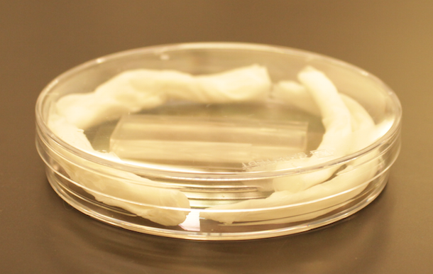
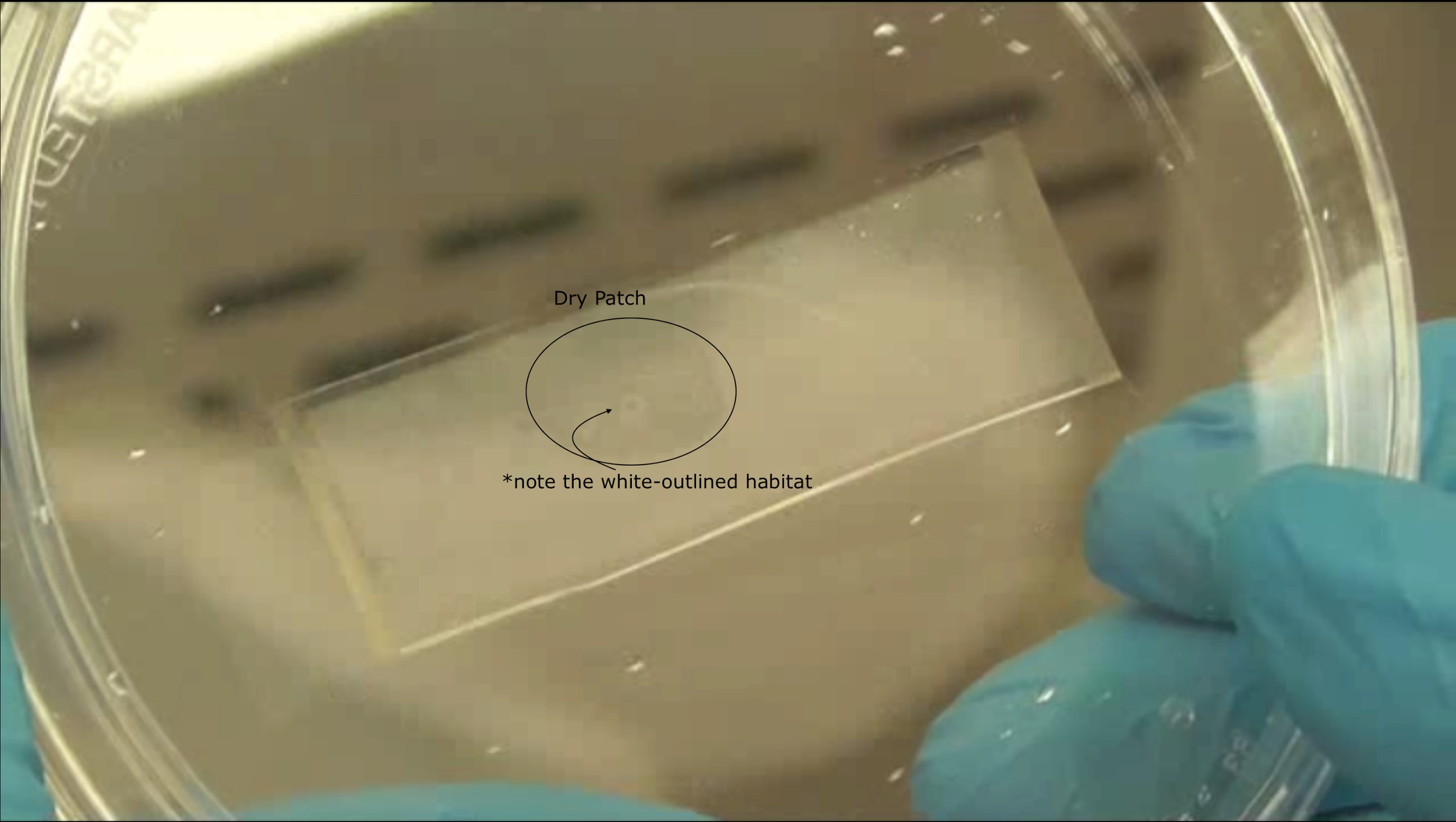
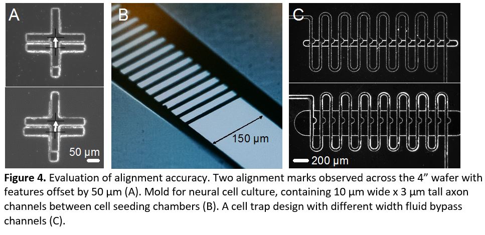
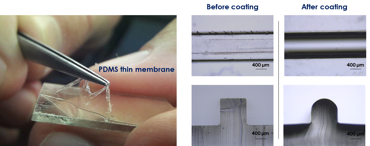
6. Verify the coating by peeling off the PDMS membrane from the glass slide by tweezer (left picture) or analyze the microchannel profile by microscopy (right panels).
What else should I know?
In this tip a portable spin coater for microfluidic applications was developed using old electronic parts. A single fan can be re-used many times (up to hundreds in our experience). The amount of PDMS (in form of droplets) falling on the fan is quite limited. If necessary the fan can be cleaned after any use by simply rubbing it with a wipe soaked with some petroleum ether (aka liquid paraffin or white petroleum). In the worst cases (very rarely occurring) the fan can be easily replaced, since they are available for free by any old unused PC.
Acknowledgements
This work was supported by the Ministère de l’Enseignement Supérieur et de la Recherche, the Université Paris-Descartes, the Centre National de la Recherche Scientifique (CNRS), the Institut National de la Santé et de la Recherche Médicale (INSERM). This work was founded by CAMPUS FRANCE (n° 39525QJ) and carried out with the support of the Pierre-Gilles de Gennes Institute equipment (“Investissements d’Avenir” program, reference: ANR 10-NANO 0207). Financial support from the Università italo-francese grant G18-208 is gratefully acknowledged.
References
[1] D. B. Hall, P. Underhill, and J. M. Torkelson, “Spin coating of thin and ultrathin polymer films,” Polymer Engineering & Science, vol. 38, no. 12, pp. 2039-2045, 1998.
[2] S. Halldorsson, E. Lucumi, R. Gómez-Sjöberg, and R. M. Fleming, “Advantages and challenges of microfluidic cell culture in polydimethylsiloxane devices,” Biosensors and Bioelectronics, vol. 63, pp. 218-231, 2015.
[3] R. Vecchione, G. Pitingolo, D. Guarnieri, A. P. Falanga, and P. A. Netti, “From square to circular polymeric microchannels by spin coating technology: a low cost platform for endothelial cell culture,” Biofabrication, vol. 8, no. 2, pp. 025005-025005, 2016 May 2016.


")