Author Archive

Rapid and easy fabrication of glass-bottom culture dishes for long-term live cell imaging

Ayako Yamada123, Jean-Louis Viovy123, Catherine Villard123 and Stéphanie Descroix123

1 Laboratoire Physico Chimie Curie, Institut Curie, PSL Research University, CNRS UMR168, Paris, France.

2 Sorbonne Universités, UMPC Univ. Paris 06, Paris, France

3 Institut Pierre-Gilles de Gennes, Paris, France

Email: ayako.yamada@curie.fr


Why is this useful?

Glass is a versatile surface for chemical treatments, and it still is by far the most used substrate for surface engineering (e.g. micropatterning, surface chemistry) or plasma-bonding of PDMS microfluidic devices. For cell culture on such substrates, glass-bottom culture dishes are desired to keep over the cells well defined medium volumes, and to protect the cells from contamination and medium evaporation. Moreover, they are optically better suited for microscopy observation than polystyrene dishes routinely used for cell culture. Although glass-bottom culture dishes are commercially available (e.g. Fluorodish from WPI), the presence of plastic walls limits the treatments that can be performed onto the glass bottom surface and those are more expensive ( 5 € per dish; φ 50 mm) than polystyrene dishes (e.g. φ 40 mm dish from TPP, 0.5 € per dish). In this Tip, we describe an easier way than a previous Tip1 to transform a polystyrene culture dish into a glass-bottom one, while preserving the possibility to apply to the glass any treatment before its assembly into a dish. Note that in this method, the body of the culture dish will be upside down and the lid is thus no longer lifted above the dish opening by lid stoppers. However, the gas exchange through the gap between the body and its lid seems to be enough to culture cells healthily in this dish. In summary, this Tip provides a low-cost and rapid solution for cell culture in a microfluidic device or on an engineered surface directly in a culture dish, suited for a long-term live cell imaging.


What do I need?      

  • φ 40 mm polystyrene tissue culture dish (e.g. TPP #93040)
  • φ 40 mm cover slide (e.g. Thermo Fisher Scientific #11757065, ∼0.2 € per slide)
  • Large screw driver (or a similar tool)
  • Uncured mixture of PDMS base and curing agent (10:1 w/w)
  • Oven or hotplate
  • Ferromagnetic metal plate (e.g. lid of a PDMS container, optional)
  • Cylindrical magnets (optional)


What do I do?

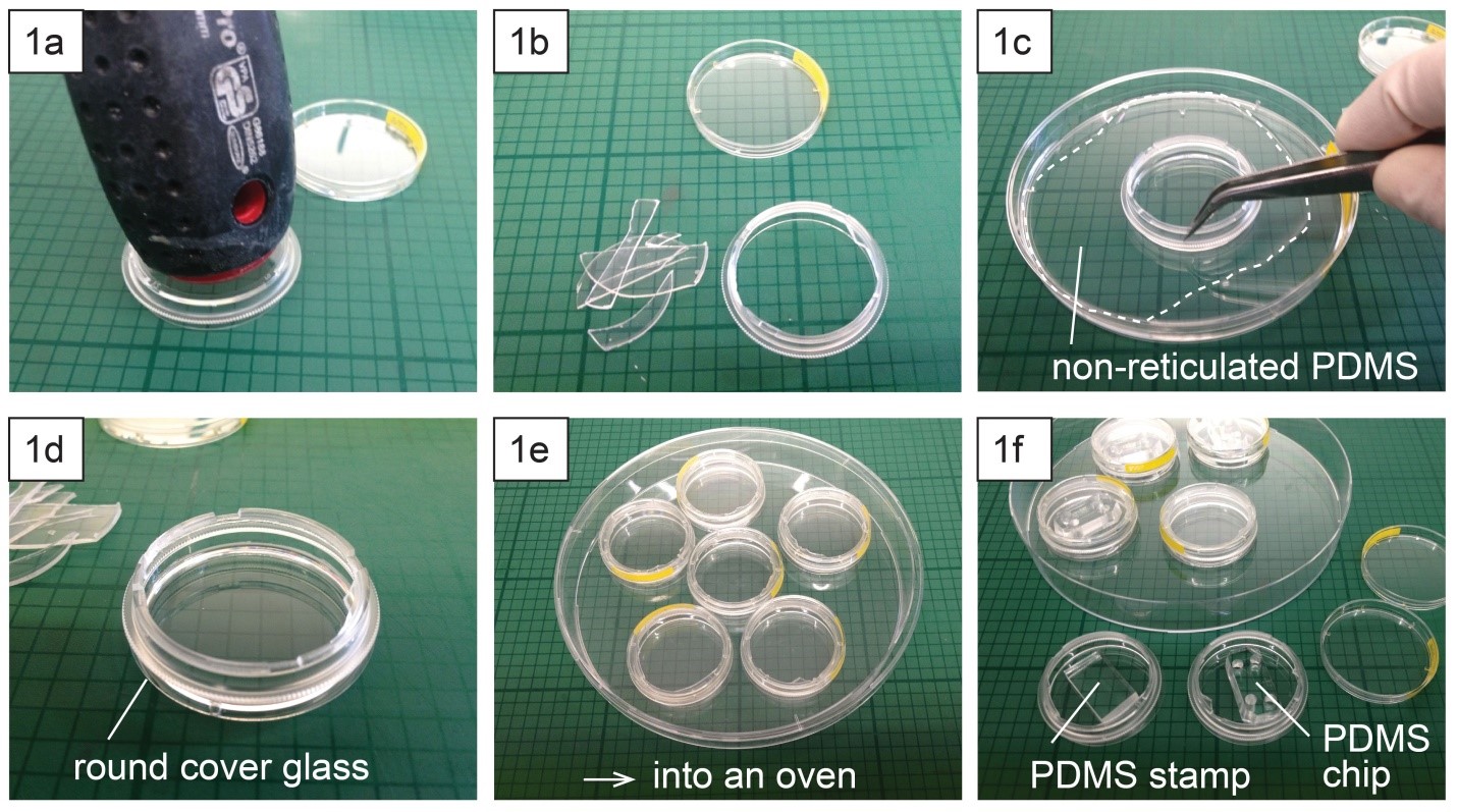
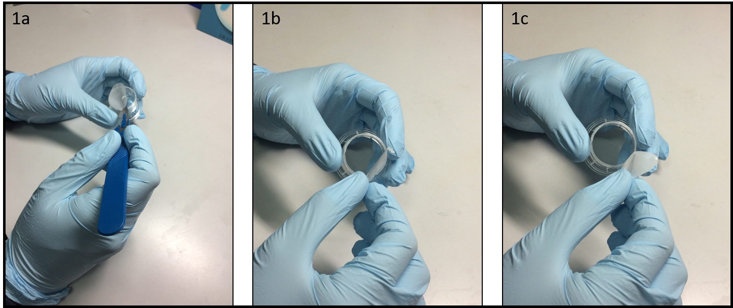
  1. Place a polystyrene culture dish upside down on a surface and hit a few times the center of the dish bottom with the grip of a large screw driver (Fig. 1a) until the dish bottom falls apart from the dish wall (Fig. 1b). The bottom should fall easily with the success rate around 9 over 10. Avoid breaking the dish wall by hitting the bottom too strongly.
  2. Spread uncured PDMS mixture on a flat substrate (e.g. a larger plastic Petri dish) and coat the edge of the dish (broken part up) with PDMS (Fig. 1c).
  3. Place the dish (broken part up) on a cover glass slide (Fig. 1d) and cure PDMS in an oven or on a hotplate e.g. at 80 °C for 10 min (Fig. 1e).
  4. Surface treatment (e.g. micro-contact printing) or plasma-bonding of a PDMS chip to the glass surface can be performed after or before the dish assembly (Fig. 1f).

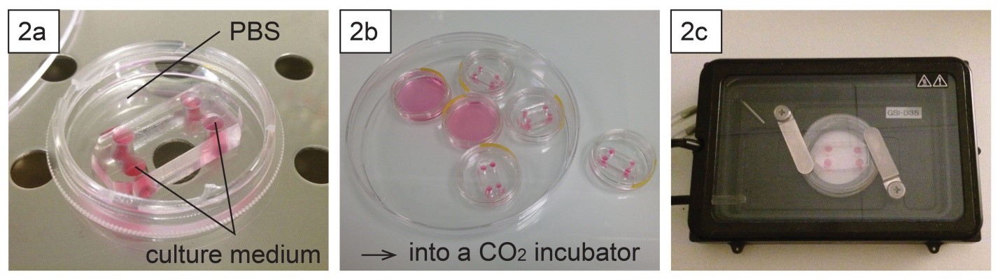
  1. To keep humidity for on-chip cell culture, the dish can be filled with e.g. phosphate buffered saline (Fig. 2a). Dishes with chips or micropatterns loaded with cells can be placed in a CO2 incubator with or without further protection (Fig. 2b).
  2. Long-term live cell imaging can be performed using a stage top incubator (Fig. 2c).


What else should I know?

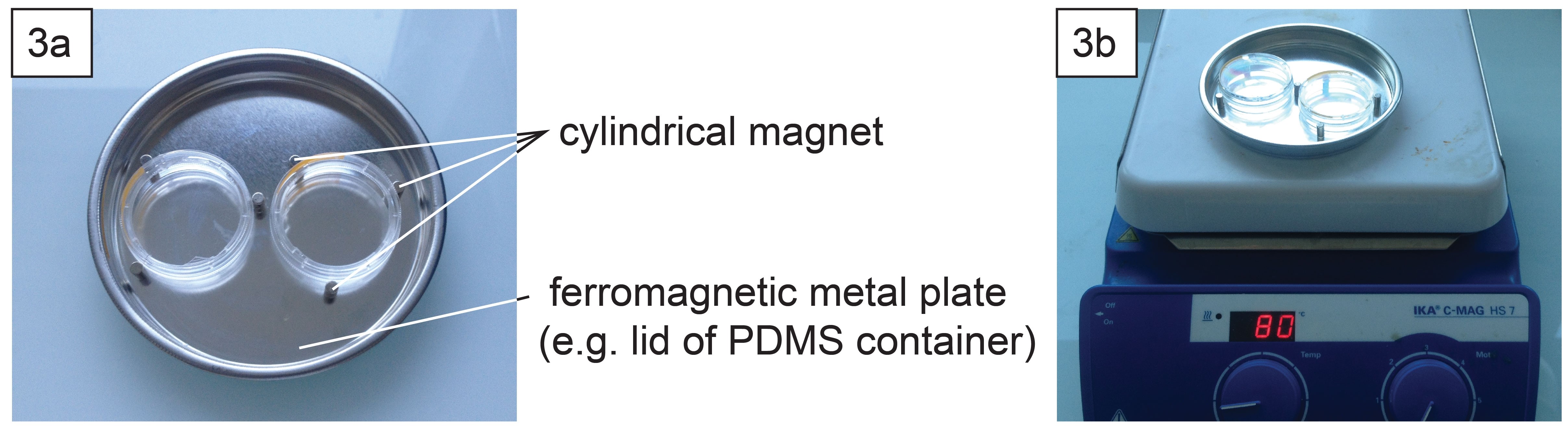
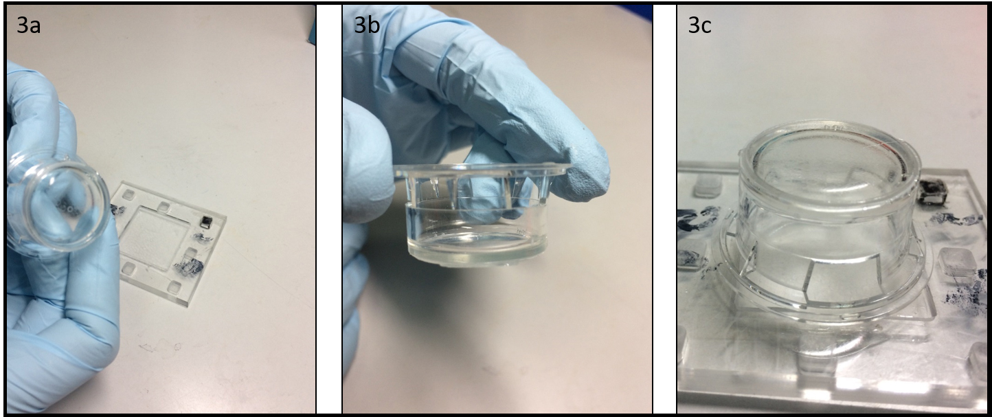
  1. Depending on the support type of microscopes, it might be necessary to well align the contours of the dish and the glass slide. This can be done using cylindrical magnets (3 per dish) and a ferromagnetic metal plate (Fig. 3a) during PDMS curing in an oven or on a hotplate (Fig. 3b).


Acknowledgement

This work is supported by the French National Research Agency (ANR) as part of the “Investissements d’Avenir” program (reference: ANR 10-NANO 0207) and ERC Advanced Grant CellO (FP7-IDEAS-ERC-321107).


Reference

[1] Caballero D, Samitier J, Different strategies for the fabrication of cell culture chambers for live-cell imaging studies. Chips and Tips, 02 Dec 2014 (https://blogs.rsc.org/chipsandtips/2014/12/02/different-strategies-for-the-fabrication-of-cell-culture-chambers-for-live-cell-imaging-studies/)


Digg This
Reddit This
Stumble Now!
Share on Facebook
Bookmark this on Delicious
Share on LinkedIn
Bookmark this on Technorati
Post on Twitter
Google Buzz (aka. Google Reader)

Multilayer photolithography with manual photomask alignment

Frank Benesch-Lee, Jose M. Lazaro Guevara, and Dirk R. Albrecht

Worcester Polytechnic Institute, Worcester, MA 01609 USA

Why is it useful?

Modern microfluidic devices can incorporate channels of different heights to fulfill their designed function. Examples include hydrodynamic focusing [1], cell traps [2], and chambers that isolate cellular components [3]. These devices are fabricated from a multilayer SU-8 photoresist master mold. Each layer height requires a separate set of photolithographic steps, including photoresist spin, photomask alignment, exposure, and bakes, followed by a development step at the end to reveal the 3D resist pattern.

Mask aligners have microscopes and stage micrometers for precise, micron-scale alignment of each layer’s photomask with visible marks on the substrate wafer.  They are indispensable tools for creating multilayer patterns with accurate registration, but while available in cleanrooms at many research universities, their substantial expense may place them out of reach of teaching institutions and individual laboratories.

In contrast, single-layer microfluidics can be prepared using an inexpensive UV light source, or even a self-made one [4]. In principle, manual photomask alignment could be made under a microscope, then brought to the UV source, yet this poses several complications. First, alignment features can be very difficult to see using inexpensive microscopes or stereoscopes, especially in thin SU8 layers, due to poor contrast between exposed and unexposed regions before development. Second, misalignment can occur during movement to the exposure system.

Here we present a manual photomask positioning method that yields a 50 µm accuracy, without the aid of a mask aligner.


What do I need?

  • Equipment and supplies for photolithography:
    • Spin coater, and UV exposure system
    • Substrate wafer and SU-8 photoresist
  • Small microscope (e.g. USB) or stereo microscope
  • Photomask transparencies for each layer
  • Scotch tape
  • Fine-tip permanent marker
  • Straight razor blade
  • Cutting mat
  • 4 small (3/4”) or mini (1/2”) binder clips
  • Glass plate, approx. 4 x 5”, compatible with exposure system


What do I do?

  • Cut the photomasks from the transparency sheet, leaving 4 corner tabs. Align the two masks relative to each other under the microscope (Figure 1a) and clip them together with a binder clip. Ensure correct mask orientation and check alignment accuracy at multiple alignment marks across the mask. (Note that horizontal alignment accuracy with a stereomicroscope is low, because each eye’s optical path is angled 5 – 8 degrees, whereas vertical alignment is unaffected. Align in the vertical direction first then rotate the masks 90 degrees to ensure accurate alignment in both horizontal and vertical directions.) Add binder clips to each corner (Figure 1b), and verify alignment. Next, remove one binder clip at a time and use a straight razor blade to cut a sharp V-notch into each tab, through both masks. Press the blade straight down to avoid shifting the alignment. Replace the binder clip, and proceed to the next corner until all 4 notches are cut (Figure 1c).


  1. Spin the first layer of SU-8 onto the wafer to the desired thickness and prebake. Attach 4 pieces of scotch tape onto the bottom of the wafer so that the sticky side faces up (Figure 2a). Position the first mask on the wafer, pressing gently to adhere it to the tape tabs. Use a fine-tip marker to trace the alignment notches (Figure 2b) onto the scotch tape (Figure 2c).  Transfer to the UV exposure system and expose.  Carefully remove the mask without detaching the scotch tape from the wafer and postbake.  Scotch tape is compatible with 95 °C baking.  Apply an additional piece of tape to cover the sticky tape tabs to protect the marker from smearing and allow smooth alignment of the next mask.


  1. Spin coat the next photoresist layer and prebake (Figure 3a). Mount the wafer onto a glass plate with a loop of scotch tape to keep it in place. Position the second mask onto the wafer, ensuring that alignment “V” markings are centered within each alignment notch and across all 4 corners (Figure 3b). Affix the mask to the glass plate with thin (2-3 mm wide) pieces of tape, and adjust alignment as necessary.  Carefully transfer the glass plate with wafer and aligned photomask for exposure (Figure 3c).


  1. Repeat step 3 for any additional layers. Remove the tape tabs and develop the photoresist. Evaluate alignment accuracy under a microscope (Figure 4).


Conclusions:

In this tip, we present a method for manual alignment of multiple transparency photomasks.  We achieved repeatable accuracy of <100 µm and as good as 50 µm (Figure 4a). These accuracies are within required tolerances of many multilayer designs (Figure 4b).  In many cases, minor design alternatives can relax alignment tolerances, such as in a trap design containing a thin horizontal channel that allows fluid bypass but captures larger objects (Figure 4c). In this example, a 100 µm wide bypass channel only partially covered the trap indentations, whereas widening the bypass channel to 400 µm enabled a functional device despite slight misalignment.  Overall, this simple method allows fabrication of microfluidic device molds containing multiple layer heights, without expensive mask alignment equipment, to an accuracy of at least 50 µm.  Furthermore, after alignment marks are cut, no microscope is needed at all during the photolithography process, speeding the fabrication of multiple masters.


Acknowledgments:
Funding provided by NSF IGERT DGE 1144804 (FBL), Fulbright LASPAU (JMLG), University of San Carlos of Guatemala (JMLG), NSF CBET 1605679 (DRA), NIH R01DC016058 (DRA), and Burroughs Wellcome CASI (DRA).Acknowledgments:


References:

  1. Chih-Chang, C., H. Zhi-Xiong, and Y. Ruey-Jen, Three-dimensional hydrodynamic focusing in two-layer polydimethylsiloxane (PDMS) microchannels. Journal of Micromechanics and Microengineering, 2007. 17(8): p. 1479.
  2. Erickson, J., et al., Caged neuron MEA: A system for long-term investigation of cultured neural network connectivity. Journal of Neuroscience Methods, 2008. 175(1): p. 1-16.
  3. Taylor, A. M., et al., A microfluidic culture platform for CNS axonal injury, regeneration and transport. Nature Methods, 2005. 2(8): p. 599-605.
  4. Erickstad, M., E. Gutierrez, and A. Groisman, A low-cost low-maintenance ultraviolet lithography light source based on light-emitting diodes. Lab on a Chip, 2015. 15(1): p. 57-61.


Digg This
Reddit This
Stumble Now!
Share on Facebook
Bookmark this on Delicious
Share on LinkedIn
Bookmark this on Technorati
Post on Twitter
Google Buzz (aka. Google Reader)

A simple, bubble-free cell loading technique for culturing mammalian cells on lab-on-a-chip devices

Sahl Sadeghi1­* and Meltem Elitas1

1 Faculty of Engineering and Natural Sciences, Sabanci University, 34956, Istanbul, Turkey

* Sahl Sadeghi wrote the paper.


Purpose

Lab-on-a-chip (LOC) devices significantly contribute different disciplines of science. Polydimethylsiloxane (PDMS) is one of the main materials, which is widely used for the fabrication of biological LOCs, due to its biocompatibility and ease of use. However, PDMS and some other polymeric materials are intrinsically water repellant (or hydrophobic), which results in difficulties in loading and operating LOCs. The eminent consequence of hydrophobicity in LOCs for biological systems is the entrapment of air bubbles in microfluidic channels. Although the oxygen plasma treatment of PDMS reduces the surface hydrophobicity for a certain period of time, the hydrophilic property of PDMS vanishes over time1. The persistent problem of bubbles in the microfluidics led to several studies conducted to overcome it. Some of these solutions suggested implementing bubble traps2,3, surface treatment of LOCs through hydrophilic coatings4, and using actively controlled bubble removal systems 5,6.

Although the aforementioned design complexities are introduced to LOCs in order to reduce the clogging problem caused by the bubbles, these modifications also result in higher production cost, complex operation, and long device preparation time. In many single-cell experiments without losing or damaging the rare cells, these cells needs to be introduce into the LOCs. Here, we present a simple method that enables loading a small number of cells without introducing bubbles in the microfluidics channels.


Materials

·         PDMS (Dow Corning Sylgard 184 Silicon Elastomer Kit)
·         Pipette tips (20-200 ul, Eppendorf, # 3120000917)
·         Pipetman (Gilson, P200, #69989-5)
·         Aqueous ethanol 70% (ZAG Chemistry)
·         Cell culture medium (DMEM, PAN Biotech, #P04-01548)
·         Mammalian cells (MCF7, ATCC-HTB-22)
·         Sterile syringe (BD 10 ml Syringe, Luer-Lok Tip, #300912)
·         Sterile Hamilton syringe (Hamilton, 100 ul SYR, #84884)


Procedure

Step 1: Insert two 200-ul pipet tips at the inlet and outlet ports of the PDMS device as illustrated in Figure 1.

Step 2: Introduce a 70% aqueous ethanol into the inlet-pipet tip using a pipetman. Thus, the inner surface of microfluidic channels will be disinfected and the fluid flow will be tested within the micro channels as it is applied in many other protocols for LOCs7,8.

Step 3: Gently apply pressure pressing the pipetman to force ethanol solution flow through the micro channels and cavities of the PDMS device. Take care to avoid applying negative pressure from the outlet-pipet tip, which might create air leakage through the pipet connections. Besides, applying a negative pressure will directly affect the amount of a gas dissolved in the liquid according to Henry’s law9 that might contribute formation of more bubbles inside the micro-channels. The positive pressure will facilitate removal of the air bubbles via dissolving them.

Step 4: After flushing the chip with ethanol solution, inspect the chip to ensure bubble removal. In case of air bubbles, repeat the steps 2 and 3.

Step 5: Fill the syringe (10 ml) with medium or phosphate buffered saline (PBS). Take care to remove the air bubbles inside the syringe, mount and lock the needle on the syringe. Then, flow medium through the needle too make sure the needle is full of medium without any bubble. Insert the needle in the inlet-pipet tip; gently apply positive pressure to replace the ethanol with medium. Next, collect the excess medium from the outlet-pipet tip.

Step 6: Fill the inlet pipet with fresh medium in such a way that due to certain height (h) between the levels of the medium in the inlet and outlet pipet tips, very slow medium flow will be established inside the micro-channels.

Step 7: Load your cells into the Hamilton syringe and take care to ensure that there is no air bubble inside its needle and syringe. Insert the needle of the Hamilton syringe into the inlet-pipet tip as explained in Step 5, Figure 1. Introduce the cells via applying gentle positive pressure to the syringe. Established flow streams in the PDMS chip will deliver the released cells to the desired positions in the chip. Flow rate can be arranged adjusting the applied positive pressure and amount of medium collected in the inlet and outlet pipet tips. The excess supernatant from the outlet-pipet tip can be collected, and fresh medium can be supplied through the inlet-pipet tip during the experiment.


References

  1. Tan, S.H., N.T. Nguyen, Y.C. Chua, and T.G. Kang,. Biomicrofluidics, 2010. 4(3).
  2. Zheng, W.F., Z. Wang, W. Zhang, and X.Y. Jiang,. Lab on a Chip, 2010. 10(21): p. 2906-2910.
  3. Wang, Y., D. Lee, L.S. Zhang, H. Jeon, J.E. Mendoza-Elias, T.A. Harvat, S.Z. Hassan, A. Zhou, D.T. Eddington, and J. Oberholzer, . Biomedical Microdevices, 2012. 14(2): p. 419-426.
  4. Wang, Y.L., C.E. Sims, and N.L. Allbritton,. Lab on a Chip, 2012. 12(17): p. 3036-3039.
  5. Karlsson, J.M., M. Gazin, S. Laakso, T. Haraldsson, S. Malhotra-Kumar, M. Maki, H. Goossens, and W. van der Wijngaart,. Lab on a Chip, 2013. 13(22): p. 4366-4373.
  6. Cortes, D.F., T.-X. Tang, D.G.S. Capelluto, and I.M. Lazar,. Sensors and Actuators B: Chemical, 2017. 243: p. 650-657.
  7. Benavente-Babace, A., D. Gallego-Perez, D.J. Hansford, S. Arana, E. Perez-Lorenzo, and M. Mujika,. Biosensors & Bioelectronics, 2014. 61: p. 298-305.
  8. Yesilkoy, F., R. Ueno, B.X.E. Desbiolles, M. Grisi, Y. Sakai, B.J. Kim, and J. Brugger,. Biomicrofluidics, 2016. 10(1).
  9. Henry, W., Phil. Trans. R. Soc. Lond., 1803. 93: 29–274.

Figure 1 – Schematic of cell loading procedure in a microfluidic PDMS device.


Digg This
Reddit This
Stumble Now!
Share on Facebook
Bookmark this on Delicious
Share on LinkedIn
Bookmark this on Technorati
Post on Twitter
Google Buzz (aka. Google Reader)

A novel low cost method to prepare a cross-linked gelatin membrane for potential biological applications

Gabriele Pitingolo1 and Valerie Taly1

 1 INSERM UMRS1147, CNRS SNC 5014, Université Paris Descartes, Equipe labellisée Ligue Nationale contre le cancer 2016. Paris, France.

email: gabriele.pitingolo@parisdescartes.fr


Why is this useful?

In recent years, several gelatin types (i.e. GelMA, A or B) have been used in pharmaceutical formulation and tissue engineering due to their excellent biocompatibility, propensity to cell differentiation and availability at low cost.1 The use of gelatin as biomaterial is also advantageous for the possibility to tune the mechanical properties of the substrate, changing the concentration in water and the degree of cross-linking. However, Transwell® is the most used permeable support with microporous membranes and is a standard method for culturing cells.2 This commercial type of support has been widely used to study the molecular secretion by different cell types and also to reproduce several in vitro physiological barriers (i.e. blood brain barrier).3 Transwell® cell culture inserts are convenient, because they are sterile and easy-to-use, but they are very expensive (~ 300 $ for a 12 pack) and possess a limited range of biomaterial properties because they are made from polyester or polycarbonate. Furthermore, as shown by Falanga and colleagues, these porous membranes are often integrated onto microfluidic chip for permeability studies.4

Recently, Yong X. Chen et al. proposed an alternative method to prepare a suspended hydrogel membrane platform for cell culture, designing a complicated protocol to synthesize the GelMA and to fabricate an open-grid structure made of polylactic acid (PLA) polymer using a commercial printer.5 Our tip shows a novel low-cost method for preparing a cross-liked gelatin membrane as a permeable support useful for potential biological applications. In addition, the proposed protocol doesn’t require the use of sophisticated fabrication technologies or expensive materials. It uses gelatin from porcine skin and the formaldehyde vapor technique to cross-link the gelatin membrane. As proof of concept, we integrate the gelatin membrane into a microfluidic chip, to show the possibility to develop a platform for comparable studies in static and dynamic conditions.

Furthermore, to demonstrate the resistance to culture temperature (around 37° C) of the prepared gelatin membrane, we tested the mechanical properties (Young’s modulus) before and after the incubation time (2 days). Finally, we observed the preservation of the mechanical properties and structural integrity that makes the membrane usable for studies with cell culture.


What do I need?

  • Transwell insert
  • Porcine gelatin type A
  • Formaldehyde solution
  • Scalpel
  • PMMA milled chamber or similar


What do I do?

  1. Remove the porous membrane from the Transwell® insert (Fig. 1a-1c) or alternatively use a similar homemade support. To facilitate this step is convenient to use a scalpel to incise the membrane along the entire diameter.


  1. After the removal of the membrane, the Transwell® support is ready to use. Position the structure at the center of the PMMA chamber (depth 2 mm at least) (Fig 2a) and pour liquid 10% w/v gelatin, without bubbles, onto the PMMA chamber and inside the Transwell® support (Fig 2b). After 2 min of stabilization, put the system in the fridge, for at least 10 minutes.


  1. After the gelation time (10 minutes at 4°C) it is possible to remove the formed gelatin membrane from the PMMA chamber, with the aid of a scalpel to facilitate the detachment (Fig 3a-3b). As shown in Figure 3c the gelatin membrane it appears very flat, an ideal characteristic for cell cultivation (Fig 3c). To guarantee the preservation of the mechanical properties during the cell culture step, cross-link the gelatin membrane using the classical protocol “cells-biocompatible”, such as glyceraldehyde6, formaldehyde7 and glutaraldehyde8 methods or natural products such as genipin.9


  1. In this case, we used the vapor formaldehyde method to cross-link the prepared gelatin membrane and to obtain a system with lower aqueous solubility, higher mechanical strength and stability against enzymatic degradation. We exposed the gelatin membrane to formaldehyde vapors for 1 day. In Figure 4a we show the difference, after 48 h of culture conditions, between a sample cross-linked (left) and not (right). The final depth of the cross-linked gelatin membrane is around 1 mm, however, it is possible to change the depth tuning the liquid gelatin amount. Finally, we calculated, before and after the incubation time, the young’s modulus of the cross-linked gelatin membrane, observing a similar value of 40 kPa (compression test by using hydraulic testing system Instron DX).


  1. Integration of the gelatin membrane into a microchip. In this section, we detail the integration of the gelatin membrane into a microfluidic chip. As example, we used the same geometry proposed in our previous work4, to make a device for a permeability experiment (Figure 5a). As shown in Figure 5b, just pour the liquid gelatin into the smaller drilled microchannel, using a pipette to form a thin uniform layer of gelatin (Figure 5c). After gelation at 4° C, cross-link the formed gelatin membrane using the previously described method, the result is shown in Figure 5d. To bond the different PMMA-PDMS substrates we propose here a magnetic approach recently developed by our group10, to preserve the gelatin membrane by physical-chemical stress as in the case of solvent evaporation and plasma bonding. Figure 5e shows the final chip.


Conclusions: In this tip, a novel biocompatible gelatin permeable support was obtained by using a simple and low cost fabrication method. Vapor formaldehyde method or other chemical crosslinking approach can be applied to crosslink the integrated gelatin membrane for the use as potential scaffolds for cell culture. Furthermore, the Young’s modulus and the thickness of the permeable membrane can be adjusted by changing the initial concentration of the gelatin, the degree of cross linking and the amount of liquid gelatin. Finally, we showed the integration of the gelatin membrane into a modular microchip. Therefore, we propose an easy and low cost method to prepare a permeable gelatin membrane for cell biology and for other applications.


Acknowledgements

This work was carried out with the support of the Pierre-Gilles de Gennes Institute equipment (“Investissements d’Avenir” program, reference: ANR 10-NANO 0207).


References

  1. Geckil, Hikmet, et al. “Engineering hydrogels as extracellular matrix mimics.” Nanomedicine 5.3 (2010): 469-484.
  2. https://www.corning.com/worldwide/en/products/life-sciences/products/permeable-supports/transwell-guidelines.html
  3. Guarnieri, Daniela, et al. “Shuttle‐Mediated Nanoparticle Delivery to the Blood–Brain Barrier.” Small 9.6 (2013): 853-862.
  4. Falanga, A. P., Pitingolo, G., Celentano, M., Cosentino, A., Melone, P., Vecchione, R. & Netti, P. A. (2016). Shuttle‐mediated nanoparticle transport across an in vitro brain endothelium under flow conditions. Biotechnology and Bioengineering.
  5. Chen, Yong X., et al. “A Novel Suspended Hydrogel Membrane Platform for Cell Culture.” Journal of Nanotechnology in Engineering and Medicine 6.2 (2015): 021002.
  6. Sisson, Kristin, et al. “Evaluation of cross-linking methods for electrospun gelatin on cell growth and viability.” Biomacromolecules 10.7 (2009): 1675-1680.
  7. Usta, M., et al. “Behavior and properties of neat and filled gelatins.” Biomaterials 24.1 (2003): 165-172.
  8. Talebian, A., et al. “The effect of glutaraldehyde on the properties of gelatin films.” Kemija u industriji 56.11 (2007): 537-541.
  9. Bigi, A., et al. “Stabilization of gelatin films by crosslinking with genipin.” Biomaterials 23.24 (2002): 4827-4832.
  10. Pitingolo Gabriele, et al. “Fabrication of a modular hybrid chip to mimic endothelial-lined microvessels in flow conditions.” Journal of Micromechanics and Microengineering” (Accepted manuscript)
Digg This
Reddit This
Stumble Now!
Share on Facebook
Bookmark this on Delicious
Share on LinkedIn
Bookmark this on Technorati
Post on Twitter
Google Buzz (aka. Google Reader)

DIY peristaltic pump

Shannon Faley, Bradly Baer, Matthew Richardson, Taylor Larsen, and Leon M. Bellan*

Vanderbilt University, Department of Mechanical Engineering, Nashville TN, 37235, USA

*leon.bellan@vanderbilt.edu

Why is this useful?

Figure 1: Fully assembled peristaltic pump


The majority of microfluidic applications require an external pumping mechanism.  Multi-channel, individually addressable pumps are expensive, often large, and prone to failure when operated inside cell culture incubators at 95% humidity.  The number of experiments that can be run at a given time is limited by the availability and expense of pumps.  Perfusing artificial tissue scaffolds containing engineered vasculature requires long-term (days to weeks) continuous flow at low rates.  We designed an inexpensive (~$100 for 2 pumps, ~$70 for each additional set of 2 pumps) peristaltic pumping system using an Arduino- controlled stepper motor fitted with a custom 3D-printed pump head and laser-cut mounting bracket. Each pump has a footprint roughly that of the NEMA 17 stepper motor and is easily controlled individually using open source software.  Up to 64 motor shields can be stacked for a given Arduino Uno R3, each capable of supporting two stepper motors, and thus has the expansion potential to control 128 pumps in parallel.  We have successfully implemented two stacked motor shields driving four independent stepper motors. Flow rate is dependent upon both tubing diameter and step rate.  We found flow rates to range between ~50-250 μl/min for 1/16” tubing and ~500-1500 μl/min for 1/4″ tubing.  We anticipate that this pump design will likely prove more resilient to incubator humidity compared to standard peristaltic pump powered by DC motors.  Since implementation, these pumps have functioned without fail for 3 months (intermittent) under humid conditions. In the event of failure, however, cost of motor replacement is an economical $14.

Figure 2

What do I need?


Materials:

  • Nema 17 stepper motor ($14, spec, vendor)
  • Arduino Uno R3 Controller ($25, spec, vendor)
  • Arduino Motor Shield ($20, spec, vendor)
  • M3 machine screws (4) & hex bolts (4) ($1, McMaster-Carr)
  • DB9 Male & Female Solder Connectors ($9, StarTech)
  • 18AWG 4C speaker cable ($10, Monoprice)
  • Spring steel
  • ABS Filament
  • 6-32 machine screws & square nuts (3) ($1, McMaster-Carr)

Equipment:

  • 3D printer
  • Laser/Metal cutter
  • Soldering iron & solder
  • Butane torch

What do I do?


Pump head fabrication:

  1. Using ABS filament, 3D print pump head from file pumphead.crt.9
  2. Cut three 15 mm (length) sections from rigid ¼” tubing to serve as rollers.
  3. Use the three 6-32 machine screws and square nuts to assemble the tubing to pump head as shown in Figure 3.

Figure 3

Mounting bracket fabrication:

  1. Using bracket template file (2000 Pump Mount v4) and laser cutting facilities, produce a mounting bracket from spring steel, or other appropriate metal.  Note that the score line bisecting the bracket is intended to be cut at a lower power.  This line is just a marker to show where to bend the bracket in the following step.
  2. Using handheld butane torch, heat mounting bracket along score line and bend with pliers.  Repeat until mounting bracket forms a right angle (see Figure 1).

Motor Electrical Wiring: (see figure 4 for example orientation)

  1. Solder motor wires to DB9 Male Connector
  2. Solder one end of speaker wire to DB9 Female Connector
  3. Connect opposite end of speaker wire to Arduino Motor shield

Figure 4 Example of connection scheme by wire color

Pump Assembly:

  1. Use M3 machine screws to attach mounting bracket to stepper motor, with corresponding hex nuts as spacers between motor and bracket.
  2. Press fit pump head onto rotor shaft.
  3. Connect motor to Arduino using DB9 connectors

Arduino/Motor Shield Assembly:

  1. Follow assembly instructions provided by adafruit.com  (https://learn.adafruit.com/adafruit-motor-shield-v2-for-arduino/stacking-shields).  See also Figure 5.

Figure 5

Computer Control:

1. See online resources for easy starter code (https://learn.adafruit.com/adafruit-motor-shield-v2-for-arduino/install-software)

2. Load example code to control 2 stacked motor shields running four independent pumps simultaneously. (foursteppers_v2.ino)

3. Start pumping!  See  video clip for multi-pump demonstration:


Please click here to download the DIY Peristaltic Pump Files

Digg This
Reddit This
Stumble Now!
Share on Facebook
Bookmark this on Delicious
Share on LinkedIn
Bookmark this on Technorati
Post on Twitter
Google Buzz (aka. Google Reader)