Archive for the ‘Uncategorized’ Category

Easy temperature control for syringe pump by shape-memory polymer tubings

1Sabrina Banella, 1Gaia Colombo and 2Claudio Nastruzzi
Email: bnlsrn@unife.it ; clmgai@unife.it ; nas@unife.it

1 Department of Life Sciences and Biotechnology and 2 Department of Chemical, Pharmaceutical and Agricultural Sciences, University of Ferrara, Ferrara, Italy.

Why is this useful?

Considering chemical bulk reactions that take place in aqueous phase, it is always necessary to control the temperature in a range usually comprised between few degrees Celsius (typically obtained by ice bath) up to a temperature near to the boiling point of water (i.e., 70-90 °C). This aspect is also true for reactions carried out in microfluidic conditions and in this respect, it could be sometimes tricky to control the temperature of liquids pumped to the chip by a syringe pumps.

Syringe-pumps have indeed the disadvantage to be pumping systems in which the temperature of the liquid is difficult to control. This aspect is particularly relevant for some microfluidic applications in which one or more liquid phases are pumped through the chip.

For instance, in recent years, microfluidic platforms have been largely employed for the production of liposomes and other supramolecular colloidal systems. Nastruzzi et al. have indeed reviewed the use of microfluidic chips for the production of liposomes [1].

Despite the large applicability and usefulness of syringe pumps, they could present some drawbacks with respect to fine control of the temperature. In many applications, maintaining a specific temperature is indeed crucial, as in the case of saturated (i.e., hydrogenated) phospholipids that are usually soluble only at temperature above 40-50 °C. Moreover, it has to be underlined that the whole preparation process of liposomes by hydrogenated phospholipids is to be carried out at temperature above the phase transition temperature of the lipid (Tm) [2]. The control of temperature is also required for other reactions carried out in microfluidics when the reagent requires to be manipulated at 4-5 °C or in a particular range of temperature [3].

In order to possibly solve the problem of temperature control of liquids delivered by a syringe pump, we propose here a new, very low-cost and alternative approach, with respect to another system presented on Chips and Tips [4] or in the current literature [5]. The device here presented is indeed easily applicable to any type of syringe and syringe pumps.

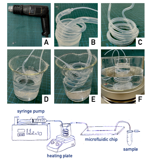
The idea is to use fluorinated ethylene propylene (FEP) tubes that, owing to their shape-memory behavior, can be heated and molded in the form of a spiral. We named these hand-made systems as “Graham temperature controller” (GTC).

What do I need?

  • Polypropylene syringe (typical volume between 5 and 50 ml) (BD Switzerland Sarl, Vaud, Switzerland)
  • 21-gauge hypodermic needle (0.80 x 40 mm; 21G x 1 ½”; PIC)
  • Tube #1 – PTFE tubing, ID 0.8 mm, OD 1.58 mm (Z609714, Sigma-Aldrich, Missouri, USA)
  • Tube #2 – Tube FEB Nat 1/8 x 0.062 x 20ft (WO#0556708, Idex Health & Science, Washington, USA)
  • Tube #3 – Tube FEP Nat 3/16 x 0.125 x 20ft (Upchurch Scientific, Washington, USA)
  • As template for spiraling the tubes different pieces of glassware and plastic commonly present in the lab can be used. For example: 10 ml test tubes with NS neck (DWK Life Sciences, New Jersey, USA) with an external diameter of 1.8 mm; 50 ml centrifuge disposable plastic conical tube plastic with an external diameter of 3 cm – plastic powder container with external diameter of 3.8 cm
  • Heat gun (Black & Decker BD1666 2 heat swing handle paintstripper or any other similar tool)
  • Glass becker fitting the external diameter of the Graham like temperature controller
  • Heating plate or ice water bath
  • 100 ml becker Scott

What do I do?

  1. After warming up the FEP tubes by a heat gun till the polymer softens (be careful not to burn your fingertips; in case use leather gloves), the tube is molded and spiraled around a template (see list of templates in the What do I need? section). Thereafter, the spiraled tube is rapidly cooled down to quench the given shape, putting it into an ice-cold water bath. In this way, the rapid cooling of the tubing allows to retain the shape given since it was warm. As said, this feature is due to the peculiar mechanical properties of FEP polymer that is characterized by a shape-memory behavior.
  1. Once the GTC is produced, it can be connected to the syringe pump (via the Luer lock male connector on one side) and to the chip (via the inlet tube of the microfluidic network). Typically, the connecting tubes are produced by smaller diameter tubes such as Tube #1 (see Figure).
  2. The GTC can be fitted in any suitable liquid container, such as a 100 ml glass becker or a 50 ml plastic centrifuge tube. As an example, if conditions above the room temperature are required (40-80 °C), the becker is then placed on a heating plate or in a boiling water bath. Analogously, if conditions lower than room temperature are required, an ice-cold water bath can be employed.
  3. Before operating the syringe pump, typically the liquid is left into the GTC for 10 minutes in order to assure that the liquid in the spiraled tube reaches the desired temperature.

This tip can be easily tuned varying the volume of the spiraled tube, using tube sections of different lengths or tubes with larger internal diameter.

Tube type Tube length (mm)
10 20 30
#1 50 100 150
#2 184 368 552
#3 750 1500 2250

Reported data indicate the volume, expressed in microliters, contained by different length of tubings.

Application note

As an example of application of the GTC, below is reported the experimental procedure relative to the preparation of liposomes composed of hydrogenated phosphatidyl choline (HPC), using an ethanol injection protocol in a chip with a flow focusing geometry [1].

Experimental procedure

Typically, a “cross-flow” chip is employed for the preparation of liposomes. Liposomes were prepared by injecting a lipid mixture (HPC 90 mM, Phospholipon 90 H, Lipoid GMBH, Ludwigshafen, Germany) dissolved in a mixture of ethanol/water (95:5, v/v), heated at 60 °C by the GTC. The lipid solution was injected into the central channel of the microfluidic network of the chip, whereas water was injected into two oblique side channels intersecting with the central one. The flow rate ratio (FRR), defined as the ratio between the water volumetric flow rate and the ethanol volumetric flow rate, was varied from 10 to 50. Liposomes can be prepared by changing also the total flow rate (TFR), typically from 18.75 to 75.00 μl/min.

References

  1. Carugo D, Bottaro E, Owen J, Stride E, Nastruzzi C. Liposome production by microfluidics: potential and limiting factors. Sci Rep., 6:25876 (2016).
  2. Chen W, Duša F, Witos J, Ruokonen SK, Wiedmer SK. Determination of the Main Phase Transition Temperature of Phospholipids by Nanoplasmonic Sensing. Sci Rep., 8(1):14815 (2018).
  3. Shen J, Liao J, Liu H, Liu C, Li C, Cheng H, Yang H, Chen H. A low-temperature digital microfluidic system used for protein-protein interaction detection. Lab Chip., 23(20):4390-4399 (2023).
  4. Capretto L, Mazzitelli S, Nastruzzi C. An easy temperature control system for syringe pumps. Chips and Tips (2008).
  5. Cantoni F, Werr G, Barbe L, Porras AM, Tenje M. A microfluidic chip carrier including temperature control and perfusion system for long-term cell imaging. HardwareX, 10:e00245 (2021).
Digg This
Reddit This
Stumble Now!
Share on Facebook
Bookmark this on Delicious
Share on LinkedIn
Bookmark this on Technorati
Post on Twitter
Google Buzz (aka. Google Reader)

A simple Matrigel cooling setup for optimal cell seeding of microfluidic devices

Torben Roy

MeBioS biomimetics group, KU Leuven, Willem de Croylaan 42, 3001 Leuven, Belgium

Why is this useful?

Some organ-on-a-chip models require seeding of cells suspended in an extracellular matrix (ECM) such as Matrigel.1-3 When seeded inside microfluidic channels, cells experience shear stresses due to mechanical forces of the fluid which can have a negative effect on the viability of the cells.

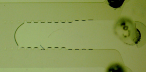
Matrigel starts to polymerize at a temperature above 10 °C, which hinders the injection of the ECM inside microfluidic channels due to an increase in viscosity. An increase in pressure from the pipette or pump is then required and if not met, the microfluidic channel will not be fully deposited as intended (Figure 1). Precautions including the cooling of the ECM solution, pipette tips and microfluidic chip need to be taken to ensure proper deposition.

A study by Kane et al. found that a temperature between 8 °C and 10 °C is ideal for cell seeding as in this temperature range a minimal shear stress is observed.4 Below 8 °C an increase in shear stress is observed due to temperature induced liquefaction, while above 10 °C polymerization induces a higher rate of shear stress. Thus to ensure maximum cell viability, it is recommended to seed a microfluidic device with a cell-Matrigel solution in the 8 – 10 °C range. The use of an ice bath or current commercial coolers does not allow for stable cooling in that temperature range.

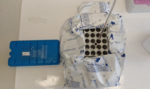
A new method is presented that allows for cooling of a cell-Matrigel solution in the optimal temperature window (8 – 10 °C). The cooling setup is composed out of a heating block (from a dry block heater) (or CoolRack™ from Corning), ice packs and a thermometer. Ice packs are less efficient at cooling compared to the ice bath and can be added and removed until a desired stable temperature is obtained. While the metal heating block (common lab equipment) allows for a homogeneous spread of the temperature.

Figure 1 – Unsuccessful deposition of a microfluidic chip with Matrigel. The Matrigel solution did not fill the entire main channel as intended due to premature polymerization.


What do I need?

  • Heating block (e.g. modular heating block for vials, VWR) or CoolRack™ (Corning)
  • Ice packs
  • Cooling element
  • Thermometer
  • Matrigel® Basement Membrane Matrix, Phenol Red-Free, LDEV-Free (356237, Corning)
  • Eppendorf tube
  • Pipette
  • Pipette tips


How do I do it?

  1. Prepare the cell-Matrigel solution in a sterile environment, aliquot in an Eppendorf tube and place on ice.
  2. Place the heating block, (autoclaved) pipette tips and (autoclaved) microfluidic chip inside the fridge to cool to 4°C.
  3. Remove the heating block from the fridge, place it on a cooling element (stable surface) and surround the heating block with ice packs.
  4. Place the Matrigel-cell solution and thermometer inside the heating block holes.
  5. Add or remove ice packs until a stable temperature in the 8 – 10°C range is achieved.
  6. Remove the microfluidic chip from the autoclave insert and place it on a cooling element. Inject the Matrigel-cell solution using cooled pipette tips.


Figure 2 – Cooling setup. A heating block is surrounded by ice packs to reach a stable temperature in the 8 – 10°C temperature range.

References

  1. Wang Y, Wang L, Guo Y, Zhu Y, Qin J. Engineering stem cell-derived 3D brain organoids in a perfusable organ-on-a-chip system. RSC Advances. 2018;8(3):1677-1685.
  2. Trietsch S, Israëls G, Joore J, Hankemeier T, Vulto P. Microfluidic titer plate for stratified 3D cell culture. Lab on a Chip. 2013;13(18):3548.
  3. Moreno E, Hachi S, Hemmer K, Trietsch S, Baumuratov A, Hankemeier T et al. Differentiation of neuroepithelial stem cells into functional dopaminergic neurons in 3D microfluidic cell culture. Lab on a Chip. 2015;15(11):2419-2428.
  4. Kane K, Moreno E, Lehr C, Hachi S, Dannert R, Sanctuary R et al. Determination of the rheological properties of Matrigel for optimum seeding conditions in microfluidic cell cultures. AIP Advances. 2018;8(12):125332.
Digg This
Reddit This
Stumble Now!
Share on Facebook
Bookmark this on Delicious
Share on LinkedIn
Bookmark this on Technorati
Post on Twitter
Google Buzz (aka. Google Reader)

Solvent Extraction of 3D Printed Molds for Soft Lithography

Jonathan Tjong1, Alyne G. Teixeira1 and John P. Frampton1,2

1School of Biomedical Engineering, Dalhousie University, Halifax, NS, Canada

2Department of Biochemistry and Molecular Biology, Dalhousie University, Halifax, NS, Canada

Why Is This Tip Useful?

Casting polydimethylsiloxane (PDMS) in molds produced from additive manufacturing (i.e., 3D printing) enables rapid prototyping of parts with microscale features without the need for conventional photolithography. Whereas conventional photolithography followed by soft lithography involves the use of silicon substrates and photomasks, which can be costly and may require special preparation and processing (e.g., application and removal of photoresist in a clean room environment), the emergence of stereolithographic 3D printers allow for the rapid manufacture of masters for PDMS casting in almost any laboratory space. Stereolithographic 3D printers use photopolymer resins that when cured can withstand temperatures as a high as 200 °C without plastic deformation, which occurs with thermoplastics such as polystyrene that have glass transition temperature around 95-105 °C (Lerman et al.). The ability to withstand such high temperatures opens the possibility for PDMS and other silicone elastomers to be cured quickly and also provides the possibility for greater control of the mechanical properties of the elastomers (Johnston et al.). However, the components within the 3D printed resin mold such as residual photoinitiators and unreacted oligomers may interfere with the curing of PDMS, resulting in incomplete curing at the interface of the printed mold and the PDMS part. Here, we demonstrate a simple treatment to remove these unwanted materials through solvent extraction.

What Do I Need?

  • Stereolithographic 3D printer and appropriate resin
  • Leak-proof, sealable container large enough to hold the 3D-printed mold
  • Dishwashing detergent
  • 95% ethanol or isopropanol
  • Orbital shaker table
  • Uncured PDMS base and curing agent (10:1 w/w)
  • Post-curing UV lightbox

What Do I Do?

  1. After cleaning and post-curing of the 3D-printed mold in the UV lightbox, place the mold in the container and add enough solvent to submerge the part.
  2. Seal the container and leave on a shaker table for 24 hours.
  3. Discard the old solvent and add new solvent. Seal and agitate for another 24 hours.
  4. Remove the part from the solvent and allow to air dry at room temperature.

What else should I know?

The exact composition of photopolymer resins for stereolithography may vary significantly between different manufacturers; therefore, it may be necessary to adjust the protocol (e.g., the type of solvent). In addition, larger prints will likely require more solvent and a longer duration of solvent extraction to account for the increased migration time of unwanted components from the print to the free solvent.

To demonstrate our procedure, we printed two sets of 5 identical molds with basic geometric features. One set used 1 mm thick outer walls, while the other set used 3 mm thick outer walls (Figure 1). The molds were designed using Onshape (Onshape, Cambridge, MA) CAD software and printed using a B9Creator v1.2 (B9Creations, Rapid City, SD) stereolithographic 3D printer. For all prints, we used B9-R2-Black resin from B9Creations. This resin is documented by the manufacturer as having a heat deflection temperature of 65 °C at 0.45 MPa determined through ISO 75-1/2:2013 standards (B9Creations). As no significant mechanical load would be placed on the resin molds (with a maximum depth of 6 mm for the PDMS chamber), we decided this resin was suitable for our test molds. After printing, excess resin was removed from the molds by submerging and agitating in an approximately 1:10 mixture of Dawn dishwashing detergent and water in a 1 L container. This was followed with additional cleaning by rinsing with excess isopropanol using a wash bottle until no visible evidence of uncured resin was present on the surface (approximately 10-20 mL per part). The molds were then post-cured in a UV lightbox for 20 minutes.

Once post-cured, the molds were each placed in new, 15 mL polypropylene centrifuge tubes (Falcon® Corning, Corning, NY) with 10 mL of the test solvents (reverse osmosis-treated (RO) water, isopropanol, 95% ethanol, or methanol), and exposed to the two 24-hour extraction procedures listed in the “What Do I Do” section. After extraction, the molds were briefly rinsed with RO water and allowed to air dry for 1 hour. Then, approximately 0.4 mL or 1 mL of premixed 10:1 uncured PDMS and curing agent were added to the 1 mm and 3 mm molds, respectively. The PDMS parts were heat-cured in a dry oven at 65 °C overnight. The cured PDMS parts were then carefully removed from the mold using a stainless-steel spatula. Images were taken using the default settings on an iPhone 7 camera.

Resin molds that did not undergo extraction or that underwent extraction in water or methanol produced PDMS parts with major defects. For these extraction conditions, fragments of semi-cured and traces of uncured PDMS remained at the PDMS-mold interface (Figure 2A-C). Extraction with methanol appeared to weaken the cured resin, with significant softening and the appearance of cracks on these molds (Figure 2C), and while the cured PDMS easily released from the methanol-extracted molds, this left artifacts on the PDMS surface. We found that resin parts pretreated with either isopropanol or 95% ethanol performed well as molds for PDMS. The cured PDMS parts easily released from the substrates, with no visible traces of uncured PDMS (Figure 2D-E), and the PDMS parts we retrieved cleanly replicated the features of the resin mold (Figure 3). In addition to producing defects in the mold itself, extraction with methanol also led to bubbles forming in the PDMS as it cured (Figure 3C). Overall, PDMS casts were most easily released from the 1 mm-thick molds compared to the 3 mm-thick molds, but this may simply be due to the lower aspect ratio (h/l) of the 1 mm-thick molds.

Take Home Message

When casting PDMS parts from molds produced by stereolithography, incomplete curing and defects in the PDMS part can be minimized by extracting residual photo-initiators and oligomers present in the mold using either isopropanol or 95% ethanol.


References

B9Creations. Black Resin Material Properties. 2018, pp. 9–11, https://cdn2.hubspot.net/hubfs/4018395/Material Data Sheets/B9Creations Black Material Properties.pdf.

Johnston, I. D., et al. “Mechanical Characterization of Bulk Sylgard 184 for Microfluidics and Microengineering.” Journal of Micromechanics and Microengineering, vol. 24, no. 3, 2014, doi:10.1088/0960-1317/24/3/035017.

Lerman, Max J., et al. “The Evolution of Polystyrene as a Cell Culture Material.” Tissue Engineering – Part B: Reviews, vol. 24, no. 5, 2018, pp. 359–72, doi:10.1089/ten.teb.2018.0056.


Figures and Legends


Figure 1. Design features of molds produced by stereolithography. Top panels in (A) and (B) are the Onshape renderings. Bottom panels in (A) and (B) are parts printed in the B9Creations B9-R2-Black resin.

Figure 2. Molds produced by stereolithography following extraction in various solvents. Fragments of partially cured PDMS and uncured PDMS remain on the surface of molds that have not undergone extraction, as well as those extracted in RO-water and methanol. Isopropanol and 95% ethanol extraction produce molds that can be re-used numerous times for PDMS curing.

Figure 3. PDMS parts obtained from curing in resin molds extracted using various solvents. Extraction of residual photo-initiators and oligomers present in the mold prior to soft lithography using either isopropanol or 95% ethanol results in clean PDMS parts that are free of defects.

Digg This
Reddit This
Stumble Now!
Share on Facebook
Bookmark this on Delicious
Share on LinkedIn
Bookmark this on Technorati
Post on Twitter
Google Buzz (aka. Google Reader)

Cutting the cords: Two paths to well-plate microfluidics

Sara E. Parker1 and Peter G. Shankles2, Maddie Evans1, Scott T. Retterer1,2,3

1 Biosciences Division, Oak Ridge National Laboratory, Oak Ridge, TN

2 The Bredesen Center, The University of Tennessee, Knoxville, TN

3 The Center for Nanophase Materials Sciences

Why is this useful?

Even simple microfluidic devices often require complex and expensive pumping and valving systems for accurately metering and controlling fluid flow. This often necessitates substantial and time-consuming set-up, and sometimes make these chips unwieldly and difficult to image. It can also represent a significant departure from the rather straight forward process of pipetting fluids from one small volume to another, making adoption by non-microfluidic experts unlikely. However, the development of well-plate microfluidics1,2 provides a high throughput, simplified method for studying fluid exchange and shear flow, while minimizing the set-up and need for multiple fluid connections. Creating an interface between the polystyrene (PS) plate and the polydimethylsiloxane (PDMS) fluidics presents the largest obstacle in creating these hybrid devices. Khine et al.1 utilized pressure to create a tight interface while Conant et al.2 adhered the surfaces using glue, but neither elaborated on their techniques and in practice small changes in the process can result in failed devices. Here, two techniques are detailed on consistently creating an effective interface between the well-plate and microfluidics. Resulting in individual wells that are interconnected via custom microchannels in a PDMS device attached to the bottom of the well-plate. Reagents are then added to wells and, driven through the underlying channel network into an outlet well via hydrostatic pressure or a pressure control system3,4.

With the use of this platform, flow can be introduced into traditional well-plate studies allowing various physiological conditions to be more closely mimicked. Further, the compatibility of these custom devices with well-plate microfluidic control systems provides the opportunity to precisely and dynamically control experimental conditions including temperature, pressure, and gas environment3,4. The use of multi-well plates also allows for multiple devices to be bonded in parallel to the same plate, increasing throughput without increasing the complexity of the control system5. Additionally, the familiarity and ubiquity of the well-plate platform provides a familiar platform for technical professionals within the lab and is automatically compatible with the host of microscope stage attachments already available for use with conventional well-plates.

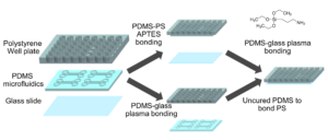
Well-plate microfluidic fabrication has been shown with a pressure seal between the microfluidics and well-plate1 as well as gluing the two together2. This work builds off these ideas by detailing bonding with a liquid adhesive or chemical activation and bonding. The process of bonding customized PDMS devices to well-plates for well-plate microfluidics has only been vaguely described previously5,6. Herein, we present two approaches that utilize either (3-Aminopropyl)triethoxysilane (ATPES) to modify the surface of the PS well-plate to bond with plasma treated PDMS, or uncured PDMS to act as a glue between the PS and PDMS surfaces7. While the APTES modification provides a stronger bond without adding additional material, the uncured PDMS bonding procedure requires less pressure, avoiding any distortion of nanoscale features. An overview of the process is shown in Figure 1:

Figure 1 – Diagram of the fabrication process with the APTES process above and PDMS glue below.

What do I need?

Materials

  • PDMS device replica with inlets and outlets designed to align with a well-plate
  • 48 well-plate; Flat-bottomed, non-tissue culture treated
  • Isopropyl alcohol (IPA)
  • Coverslip or slide large enough to cover channels
  • X-Acto knife
  • Scotch tape

APTES bonding only

  • APTES
  • Deionized water
  • Hard rubber brayer
  • Sealable plastic container

PDMS bonding only

  • Tapered tip plastic syringe (Nichiryo 6mL syringe with tips)
  • Uncured PDMS (10:1 w/w elastomer base to curing agent)

Equipment

  • Drill press
  • Plasma cleaner (Harrick Plasma, Basic plasma cleaner PDC-32G)
  • Hot plate
  • Oven (75°C)

What do I do?

Well-plate preparation (for both bonding methods)

  1. Prepare the well-plate by drilling a hole in the center of each well corresponding to an inlet or outlet on the PDMS replica (Figure 2).
  2. Using an X-Acto knife, clean the edges of the drilled holes such that the bottom surface of the well-plate is smooth and any lips that may have formed from drilling have been removed.

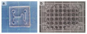
Figure 2 – The prepared PDMS device is shown in a. and the prepared well-plate is shown in b.

APTES bonding Procedure

Well-plate APTES modification

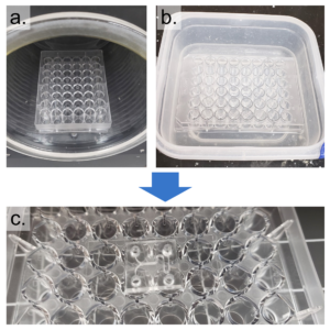
1.      Clean the bottom surface of the well-plate with IPA and expose to oxygen plasma on high setting for 2 minutes, with the bottom surface of the plate facing up (Figure 3a).

2.      In a fume hood, prepare a 100 mL aqueous solution of 1% v/v APTES and pour the solution into a shallow, resealable container.

3.      Place the plasma treated well-plate in the APTES container so that the bottom surface of the plate is completely submerged. Seal the container and let soak for 30 minutes (Figure 3b)

4.      Remove the plate from the APTES bath and rinse the top and bottom with water. Dry the well-plate using compressed air and place it on a 50°C hot plate to ensure thorough drying.

Figure 3 – The well-plate was exposed to air plasma and submerged in a water/APTES solution to modify the surface chemistry and enable bonding between PS and PDMS. A coverslip was then plasma bonded to the PDMS surface.

Assembly

1.      Clean the top of the PDMS replica (opposite to the channels) using scotch tape and plasma clean on high for 1 minute.

2.      With the channeled side of the PDMS replica facing up, align the inlets/outlets of the replica with the holes of the APTES-modified well-plate and press the layers together. Roll a brayer over the surfaces to remove any bubbles and ensure an even, uniform bond. Bake at 75°C for 20 minutes (Figure 3c).

3.      Remove the well-plate with bonded device from the oven and use scotch tape to remove debris from the channel-exposed PDMS. Clean a glass coverslip with IPA and expose the coverslip and well-plate to oxygen plasma on high for 1 minute. Bond the coverslip to the PDMS replica, thus enclosing the channels and bake at 75°C for 20 minutes.

Uncured PDMS procedure

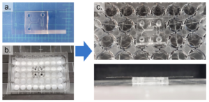
1.      Remove any dust from the bottom (channel-exposed) side of the PDMS replica using Scotch tape and clean a glass coverslip with IPA. Expose both to oxygen plasma for 1 minute on high setting and bond them together, enclosing the channels. Bake at 75°C for 1 hour (Figure 4a).

2.      Clean the bottom surface of the prepared well-plate with IPA. Using the tapered tip syringe, place small droplets of uncured PDMS onto the bottom surface of the well-plate where the PDMS device will be bonded (Figure 4b).

3.      Using scotch tape, remove any dust from the top (opposite to the channels) of the coverslip-bonded PDMS replica. Align the inlets/outlets of the device with the holes of the well-plate and lightly press the device onto the well-plate (Figure 4c). Remove any uncured PDMS that may have leaked into the wells or inlets/outlets of the device. Bake at 75°C for 1 hour.

Figure 4 – The PDMS device was first bonded to a coverslip (a) and then bonded to a well-plate using uncured PDMS (b). c shows the completed device from the top and side view.

Conclusion

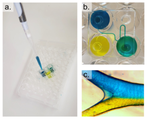
We present two methods for attaching PDMS microfluidic devices to polystyrene well-plates, providing the opportunity to utilize customized channels for well-plate microfluidics. Assays using these devices can be run in conjunction with well-plate microfluidic controllers or using simple pipetting methods by adding the desired reagent or media to the inlet wells (Figure 9). While the fabrication process is more involved than typical PDMS processing, well-plate microfluidics removes the need for complicated tubing connections by working with a single manifold controller, or hydrostatic flow using the well height to produce pressure.

References

1         M. Khine, C. Ionescu-Zanetti, A. Blatz, L. P. Wang and L. P. Lee, Lab Chip, , DOI:10.1039/b614356c.

2         C. G. Conant, M. A. Schwartz, J. E. Beecher, R. C. Rudoff, C. Ionescu-Zanetti and J. T. Nevill, Biotechnol. Bioeng., , DOI:10.1002/bit.23243.

3         Fluxion, White Pap., 2008, 1–6.

4         2012, US00825796.

5         C. G. Conant, J. T. Nevill, M. Schwartz and C. Ionescu-Zanetti, J. Lab. Autom., 2010, 15, 52–57.

6         P. J. Lee, N. Ghorashian, T. A. Gaige and P. J. Hung, J. Lab. Autom., , DOI:10.1016/j.jala.2007.07.001.

7         V. Sunkara, D.-K. Park, H. Hwang, R. Chantiwas, S. a. Soper and Y.-K. Cho, Lab Chip, 2011, 11, 962–965.


Digg This
Reddit This
Stumble Now!
Share on Facebook
Bookmark this on Delicious
Share on LinkedIn
Bookmark this on Technorati
Post on Twitter
Google Buzz (aka. Google Reader)

A second life for old electronic parts: a spin coater for microfluidic applications

Gabriele Pitingolo1, Valerie Taly1 and Claudio Nastruzzi2

1INSERM UMR-S1147, CNRS SNC5014; Paris Descartes University, Paris, France. Equipe labellisée Ligue Nationale contre le cancer.

2Dipartimento di Scienze della Vita e Biotecnologie, Università di Ferrara, Ferrara, Italia

*Email: gabriele.pitingolo@parisdescartes.fr, nas@unife.it

Why is this useful?

It is well known that the rapid proliferation of information and communications technologies (ICT) has resulted in a global mountain of high-tech trash (e-waste). The problem with e-waste is not only the accumulation of electronic products and therefore the high disposal costs, but rather the hazardous substances present in their various components. Therefore, the importance of recycling is evident in the area of resource and energy conservation, finding a new, second life for electronic components.

Spin coaters are widely used instruments useful to deposit uniform thin films to flat substrates [1]. In microfluidics, the spin coating is used to coat a photoresist layer (such as SU-8) or to bond separate substrates by using the adhesive properties of PDMS. The spin coating technology is also used to fabricate thin polymer membranes. PDMS membranes are, for example, employed for a wide range of applications due to their several advantages. For instance, being PDMS membrane permeable, they can be used to exchange gas (in cell culture application for example) or small molecule (in filtration application) [2]. In addition, as recently reported, spin coating is suitable to fabricate microchannels with a circular section [3].

Unfortunately, most commercial spin coaters are expensive (£2,000-6,000) and possess some unwanted or redundant specifications, not necessarily needed for the fabrication/modification of microfluidic devices.

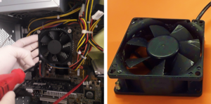
In this respect, we present here a tip to develop portable spin coaters by recycling computer fans and mobile phone wall chargers. The most common fans in personal computers have a size of 80 mm, but the size can range from 40 to 230 mm. It’s also known that the fans of different size show also a different rotational speed. Typically, the 80 mm fans have a rotational speed of 2000 rpm (that represent a suitable speed for common thin layering in microfluidics).

What do I need?

Parts for the spin coater

  • Personal computer fan
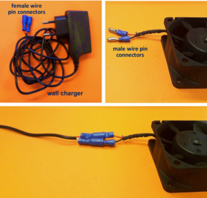
  • Insulated male/female wire pin connectors
  • Tesa power strip
  • Wall chargers from (old) mobile phones

Parts and chemicals for the specific examples

  • Milled poly(methyl methacrylate) (PMMA) microchannel
  • Glass slide
  • Sylgard® 184 silicone elastomer kit
  • Clumps

What do I do?

Assembling of spin coater

1.Remove the fan from an old pc (or mac, if are particularly posh) (Fig.1).

2. Connect the wall charger and the fan wires with insulated female and male wire pins. Afterwards, to turn on the fan, connect the female and male pins.

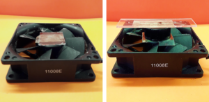
3. Using the tesa power strips, secure the substrate (i.e. glass slide or PMMA microchannel) to the central part of the fan (left picture). For devices larger than the fan, use an adeguate plastic stopper to elevate the device (right picture).

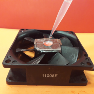
4. Drip, by a (micro)pipette, the liquid containing the coating material on top of the substrate.

5. Turn on the fan and spin coat the substrate for about 30 seconds (time can vary depending on the substrate viscosity and coating thickness required).

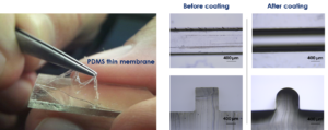
6. Verify the coating by peeling off the PDMS membrane from the glass slide by tweezer (left picture) or analyze the microchannel profile by microscopy (right panels).

What else should I know?

In this tip a portable spin coater for microfluidic applications was developed using old electronic parts. A single fan can be re-used many times (up to hundreds in our experience). The amount of PDMS (in form of droplets) falling on the fan is quite limited. If necessary the fan can be cleaned after any use by simply rubbing it with a wipe soaked with some petroleum ether (aka liquid paraffin or white petroleum). In the worst cases (very rarely occurring) the fan can be easily replaced, since they are available for free by any old unused PC.

Acknowledgements

This work was supported by the Ministère de l’Enseignement Supérieur et de la Recherche, the Université Paris-Descartes, the Centre National de la Recherche Scientifique (CNRS), the Institut National de la Santé et de la Recherche Médicale (INSERM). This work was founded by CAMPUS FRANCE (n° 39525QJ) and carried out with the support of the Pierre-Gilles de Gennes Institute equipment (“Investissements d’Avenir” program, reference: ANR 10-NANO 0207). Financial support from the Università italo-francese grant G18-208 is gratefully acknowledged.

References

[1]          D. B. Hall, P. Underhill, and J. M. Torkelson, “Spin coating of thin and ultrathin polymer films,” Polymer Engineering & Science, vol. 38, no. 12, pp. 2039-2045, 1998.

[2]          S. Halldorsson, E. Lucumi, R. Gómez-Sjöberg, and R. M. Fleming, “Advantages and challenges of microfluidic cell culture in polydimethylsiloxane devices,” Biosensors and Bioelectronics, vol. 63, pp. 218-231, 2015.

[3]          R. Vecchione, G. Pitingolo, D. Guarnieri, A. P. Falanga, and P. A. Netti, “From square to circular polymeric microchannels by spin coating technology: a low cost platform for endothelial cell culture,” Biofabrication, vol. 8, no. 2, pp. 025005-025005, 2016 May 2016.

Digg This
Reddit This
Stumble Now!
Share on Facebook
Bookmark this on Delicious
Share on LinkedIn
Bookmark this on Technorati
Post on Twitter
Google Buzz (aka. Google Reader)

Multilayer photolithography with manual photomask alignment

Frank Benesch-Lee, Jose M. Lazaro Guevara, and Dirk R. Albrecht

Worcester Polytechnic Institute, Worcester, MA 01609 USA

Why is it useful?

Modern microfluidic devices can incorporate channels of different heights to fulfill their designed function. Examples include hydrodynamic focusing [1], cell traps [2], and chambers that isolate cellular components [3]. These devices are fabricated from a multilayer SU-8 photoresist master mold. Each layer height requires a separate set of photolithographic steps, including photoresist spin, photomask alignment, exposure, and bakes, followed by a development step at the end to reveal the 3D resist pattern.

Mask aligners have microscopes and stage micrometers for precise, micron-scale alignment of each layer’s photomask with visible marks on the substrate wafer.  They are indispensable tools for creating multilayer patterns with accurate registration, but while available in cleanrooms at many research universities, their substantial expense may place them out of reach of teaching institutions and individual laboratories.

In contrast, single-layer microfluidics can be prepared using an inexpensive UV light source, or even a self-made one [4]. In principle, manual photomask alignment could be made under a microscope, then brought to the UV source, yet this poses several complications. First, alignment features can be very difficult to see using inexpensive microscopes or stereoscopes, especially in thin SU8 layers, due to poor contrast between exposed and unexposed regions before development. Second, misalignment can occur during movement to the exposure system.

Here we present a manual photomask positioning method that yields a 50 µm accuracy, without the aid of a mask aligner.


What do I need?

  • Equipment and supplies for photolithography:
    • Spin coater, and UV exposure system
    • Substrate wafer and SU-8 photoresist
  • Small microscope (e.g. USB) or stereo microscope
  • Photomask transparencies for each layer
  • Scotch tape
  • Fine-tip permanent marker
  • Straight razor blade
  • Cutting mat
  • 4 small (3/4”) or mini (1/2”) binder clips
  • Glass plate, approx. 4 x 5”, compatible with exposure system


What do I do?

  • Cut the photomasks from the transparency sheet, leaving 4 corner tabs. Align the two masks relative to each other under the microscope (Figure 1a) and clip them together with a binder clip. Ensure correct mask orientation and check alignment accuracy at multiple alignment marks across the mask. (Note that horizontal alignment accuracy with a stereomicroscope is low, because each eye’s optical path is angled 5 – 8 degrees, whereas vertical alignment is unaffected. Align in the vertical direction first then rotate the masks 90 degrees to ensure accurate alignment in both horizontal and vertical directions.) Add binder clips to each corner (Figure 1b), and verify alignment. Next, remove one binder clip at a time and use a straight razor blade to cut a sharp V-notch into each tab, through both masks. Press the blade straight down to avoid shifting the alignment. Replace the binder clip, and proceed to the next corner until all 4 notches are cut (Figure 1c).


  1. Spin the first layer of SU-8 onto the wafer to the desired thickness and prebake. Attach 4 pieces of scotch tape onto the bottom of the wafer so that the sticky side faces up (Figure 2a). Position the first mask on the wafer, pressing gently to adhere it to the tape tabs. Use a fine-tip marker to trace the alignment notches (Figure 2b) onto the scotch tape (Figure 2c).  Transfer to the UV exposure system and expose.  Carefully remove the mask without detaching the scotch tape from the wafer and postbake.  Scotch tape is compatible with 95 °C baking.  Apply an additional piece of tape to cover the sticky tape tabs to protect the marker from smearing and allow smooth alignment of the next mask.


  1. Spin coat the next photoresist layer and prebake (Figure 3a). Mount the wafer onto a glass plate with a loop of scotch tape to keep it in place. Position the second mask onto the wafer, ensuring that alignment “V” markings are centered within each alignment notch and across all 4 corners (Figure 3b). Affix the mask to the glass plate with thin (2-3 mm wide) pieces of tape, and adjust alignment as necessary.  Carefully transfer the glass plate with wafer and aligned photomask for exposure (Figure 3c).


  1. Repeat step 3 for any additional layers. Remove the tape tabs and develop the photoresist. Evaluate alignment accuracy under a microscope (Figure 4).


Conclusions:

In this tip, we present a method for manual alignment of multiple transparency photomasks.  We achieved repeatable accuracy of <100 µm and as good as 50 µm (Figure 4a). These accuracies are within required tolerances of many multilayer designs (Figure 4b).  In many cases, minor design alternatives can relax alignment tolerances, such as in a trap design containing a thin horizontal channel that allows fluid bypass but captures larger objects (Figure 4c). In this example, a 100 µm wide bypass channel only partially covered the trap indentations, whereas widening the bypass channel to 400 µm enabled a functional device despite slight misalignment.  Overall, this simple method allows fabrication of microfluidic device molds containing multiple layer heights, without expensive mask alignment equipment, to an accuracy of at least 50 µm.  Furthermore, after alignment marks are cut, no microscope is needed at all during the photolithography process, speeding the fabrication of multiple masters.


Acknowledgments:
Funding provided by NSF IGERT DGE 1144804 (FBL), Fulbright LASPAU (JMLG), University of San Carlos of Guatemala (JMLG), NSF CBET 1605679 (DRA), NIH R01DC016058 (DRA), and Burroughs Wellcome CASI (DRA).Acknowledgments:


References:

  1. Chih-Chang, C., H. Zhi-Xiong, and Y. Ruey-Jen, Three-dimensional hydrodynamic focusing in two-layer polydimethylsiloxane (PDMS) microchannels. Journal of Micromechanics and Microengineering, 2007. 17(8): p. 1479.
  2. Erickson, J., et al., Caged neuron MEA: A system for long-term investigation of cultured neural network connectivity. Journal of Neuroscience Methods, 2008. 175(1): p. 1-16.
  3. Taylor, A. M., et al., A microfluidic culture platform for CNS axonal injury, regeneration and transport. Nature Methods, 2005. 2(8): p. 599-605.
  4. Erickstad, M., E. Gutierrez, and A. Groisman, A low-cost low-maintenance ultraviolet lithography light source based on light-emitting diodes. Lab on a Chip, 2015. 15(1): p. 57-61.


Digg This
Reddit This
Stumble Now!
Share on Facebook
Bookmark this on Delicious
Share on LinkedIn
Bookmark this on Technorati
Post on Twitter
Google Buzz (aka. Google Reader)

Electric drill/driver as centrifuge with 3D-printed custom holders for non-conventional containers

Minkyu Kima, Guanya Shib, Ming Panc, Lucas R. Blaucha, and Sindy K.Y. Tanga*

aDepartment of Mechanical Engineering, Stanford University, Stanford, CA 94305, USA

bUndergradute Visiting Research Program, School of Engineering, Stanford University, Stanford, CA 94305, USA

cDepartment of Materials Science and Engineering, Stanford University, Stanford, CA 94305, USA

*sindy@stanford.edu


Why Is This Useful?

Many processes in biological and chemical preparation require centrifugation steps. The transfer of samples between the original sample container and tubes required by commercial centrifuges increases the risk of sample contamination, and often leads to the loss of samples. Commercial centrifuges are also not readily available outside laboratory settings. Here we show the design of a simple 3D-printed holder for attaching to the chuck of an electric drill/driver which we use as a centrifuge. The advantages of this method include: 1) The holder can be designed to hold non-conventional containers (e.g., syringes, glass vials, capillaries). 2) Electric drill/drivers are more widely available than centrifuges. We show that a variety of samples (e.g., water-in-oil emulsions, cell suspensions, food and drinks, wet soil) in various containers can be centrifuged with our method. This method should be useful for field work outside of the laboratory, and for the wider DIY community interested in home-based applications that require centrifugation, such as blood separation and related diagnostics, separation of interstitial water from wet soil for pollution detection, extraction and identification of allergens in food samples, and fluid clarification (e.g., olive oil, wine) by accelerating sedimentation.

What do I need?

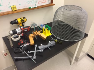
Figure 1. Photo of components needed.

  1. Electric drill/driver (DeWalt DC742KA Cordless Compact Drill/Driver Kit [1]).
  2. 3D-printed custom holder.
  3. 3D-printed custom support for the drill/driver.
  4. Four 1 mL-syringes (NORM-JECT, Part No.: 4010-200V0) as an example of non-conventional sample containers.
  5. One long bolt (Pan Head Machine Screw, Zinc, #8 x 1-1/4”) and one matching nut (Hex Nut, Zinc, #8-32). The dimensions of the bolt should match the chuck of the drill/driver.
  6. Four short bolts (Pan Head Machine Screw, Zinc, #6 x 1/2”) to secure the 1 mL-syringes to the 3D-printed custom holder.

What do I do?

  1. Design a custom holder using Solidworks or other CAD software.
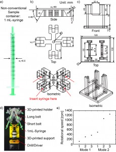
    1. Measure the outer diameter (w1 = 6.5 mm) of the 1 mL-syringe (Fig. 2a). We included a 0.5 mm-tolerance in deciding the width of the slot (w2 = 7 mm) into which the 1 mL-syringe will be secured (Fig. 2b).
    2. Decide the angle (q = 60°) at which the 1 mL-syringe will be tilted relative to the plane of rotation.
    3. Decide the length (w3 = 80 mm) and the thickness (w4 = 15 mm) of the holder.
    4. Measure or identify the outer diameters of the short and long bolts, and use these values for f3 and f5 respectively.
  2. Design a custom support for the drill/driver (Fig. 2c). The dimensions of this support are not critical so long as the drill/driver is stable and does not topple during operation.
  3. 3D-print the holder and the support. We used a 3D-printer by ROBO 3D [2]. The resolution of the 3D-printer in xyz direction is 100 mm. The material we used was polylactic acid (PLA).
  4. Assemble the centrifuge (Fig. 2d).
    1. Put one long bolt through the center of the holder and tighten with the nut.
    2. Insert the bolt into the chuck of the drill/driver and tighten the bolt by pushing the trigger of the drill/driver a few times.
    3. Make sure the bolt is fixed in the chuck and aligned to the drill/driver.
    4. Place the drill/driver in the 3D-printed support.
    5. Secure four 1 mL-syringes to the holder using the four short bolts.
  5. Start the centrifuge by pushing the trigger of the drill/driver for 5-10 minutes. The plane of rotation should be parallel to the floor.
  6. Unscrew the short bolts to remove the syringes.
  7. If desired, measure the rotational speed of the drill/driver before inserting the real samples. We used the SLO-MO mode in iPhone to calibrate the rotational speed of the drill/driver [3] (Fig. 2e).
  8. Results (Fig. 3).
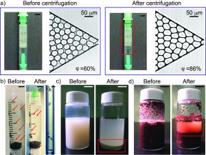
    1. Water-in-oil emulsion: Micron-sized uniform water-in-oil droplets were collected in a 1 mL-syringe. After a needle was connected to the syringe, the syringe was secured to the 3D-printed holder with needle pointing up. The holder was balanced before centrifugation by adding another syringe containing an equal weight of fluids to the opposite side of the holder. We centrifuged the sample at a speed of 374 rpm for 10 minutes. Droplets were then injected into a microchannel to measure the change of volume fraction before and after centrifugation. The volume fraction was defined as the ratio of the total volume of water droplets to the total volume of fluids filling up the channel. After centrifugation, the volume fraction of the emulsion increased from 60% to 86% without a change in the size of the droplets. Neither break-up nor coalescence of the droplets was observed.
    2. Stentor coeruleus: To demonstrate the concentration of cell suspensions, we used Stentor coeruleus (www.carolina.com) as a model. We filled a 3 mL-syringe with about 20 Stentor cells suspended in 2 mL of aqueous culture media (concentration ~ 10 cells/mL). A needle was connected to the syringe which was then secured in the 3D-printed holder with the needle pointing down. The cell suspension was centrifuged at a speed of 374 rpm for 5 min. The cells were concentrated at the bottom, close to the entrance into the needle. It was then possible to inject this concentrated cell suspension through the needle into a polyethylene tubing. Fig. 2-i) shows the microscopic image of the cells in about 15 mL of aqueous culture media in the tubing (concentration ~ 400 cells/mL).
    3. Korean rice wine (Makgeolli): A separate holder was designed to hold a 20 mL-glass vial. The vial was filled with 12 mL of Korean rice wine and centrifuged at a speed of 1252 rpm for 10 minutes. The sediment was clearly observed after centrifugation. On the other hand, the sediment was not observed for more than 20 minutes without centrifugation.
    4. Wet soil: 10 mL of wet soil in a 20 mL-glass vial was centrifuged at a speed of 1252 rpm for 10 minutes. Interstitial water was separated from the soil.

Figure 2. a) A 1-mL syringe as non-conventional container. b) Drawing of 3D-printed holder generated by SolidWorks. c) Drawing of 3D-printed support generated by SolidWorks. d) Photograph of experimental setup. The 3D-printed holder was connected to the drill/driver placed on the 3D-printed support. Four 1 mL-syringes were then tightened using the short bolts. e) Calibration plot of the rotational speed versus the trigger levels on different modes of the drill/driver. Mode 1 and Mode 2 indicate different gear settings in the transmission of the drill/driver. The numbers 1 to 3 in each mode indicate user-defined trigger levels. The rotational speed ranges from 120 rpm to 1252 rpm. The rotational speeds were measured using SLO-MO function in iPhone 6.

Figure 3. a) Photographs of emulsion in 1 mL-syringe and microscopic images of emulsion injected into a microchannel before and after centrifugation. The scale bar in the photographs is 5 mm. b) Photographs of Stentor cells in 3 mL-syringe before and after centrifugation. The red arrows indicate individual cells. The scale bar is 5 mm. i) Microscopic image of 6 Stentor cells in a polyethylene tubing after centrifugation. The scale bar is 300 mm. c) Photographs of Korean rice wine in 20 mL-glass vial before and after centrifugation. The red box indicates sediments. The scale bar is 10 mm. d) Photographs of wet soil in 20 mL-glass vial before and after centrifugation. The red box shows interstitial water separated from wet soil. The scale bar is 10 mm.


What else should i know?

  1. The centrifugal force can be increased by lengthening the arms (w3) holding the containers.
  2. The rotational speed can be measured using a high-speed camera or a smart phone with slow-motion videotaping capability, so long the frame rate is sufficient for the rotational speed used.
  3. The load in the centrifuge should be balanced.
  4. For safety purposes, safety goggles should be worn. The centrifuge should also be placed inside a safety barrier (e.g., a sturdy laundry basket). The safety instructions for the drill/driver should also be observed.
  5. After centrifugation for 10 minutes, we found that the drill/driver started to heat up. If centrifugation time longer than 10 minutes is needed, it should be possible to perform multiple rounds of 10-min centrifugation steps with breaks in between to cool down the drill/driver.

Conclusion
In this work, we demonstrated that 3D-printed holders attached to an electric drill/driver can be used for the centrifugation of samples in non-conventional containers. As 3D-printers and hand drills are easily accessible, we expect this tip to find immediate use in settings outside laboratories for field work, and also at home for DIY users.

    Acknowledgements

    We acknowledge support from the Stanford Woods Institute for the Environment and the National Science Foundation (Award #1454542 and #1517089).

    References

    1. http://www.dewalt.com/products/power-tools/drills/drills-and-hammer-drills/12v–38-10mm-cordless-compact-drilldriver-kit/dc742ka

    2. http://store.robo3d.com/collections/all/products/r1-plus-3d-printer?variant=6274616835

    3. http://www.imore.com/how-to-record-video-iphone-ipad


Digg This
Reddit This
Stumble Now!
Share on Facebook
Bookmark this on Delicious
Share on LinkedIn
Bookmark this on Technorati
Post on Twitter
Google Buzz (aka. Google Reader)

Simple and Low-cost Contact Angle Measurements Using a Smartphone with a PDMS-Lens

Jonas M. Ribea, Nils R. Skovb, Ole-Andreas K. Kavlia, Armend G. Håtia, Henrik Bruusb and Bjørn T. Stokkea

a Department of Physics, Norwegian University of Science and Technology, NO–7491 Trondheim, Norway

b Department of Physics, Technical University of Denmark, DK–2800 Kongens Lyngby, Denmark

jonas.ribe@ntnu.no


Why Is This Useful?

Contact angle measurements are important for characterizing the wettability of a liquid to a solid surface. In microfluidics they are of special interest as they provide insight into the intermolecular interactions between the sample liquid and the microchannel surface. Contact angle measurements are also important when assembling polydimethylsiloxane (PDMS) devices using oxygen plasma bonding. For optimal bond strength the water contact angle of plasma treated PDMS should be minimized as shown by Bhattacharya et al. [1] A current hurdle in measuring contact angles is the requirement of a setup that is expensive and non-portable. Here we show a method for measuring contact angles using materials and equipment found in a typical microfluidics lab.

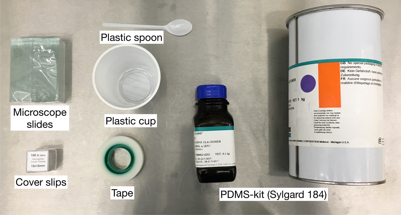
What do I need?

Consumables:

Equipment:

  • Smartphone
  • Digital scale
  • Desiccator with vacuum pump
  • Oven
  • Syringe pump (optional)
  • Light source

For measurements:

  • Pipette (0.5–3μL)
  • Sample (e.g. deionized (DI) water or other liquid sample)

What do I do?

Prepare PDMS:

  1. Weigh 10:1 PDMS (Sylgard 184) in a plastic cup on the digital scale
  2. Mix the PDMS by hand using a plastic spoon
  3. Degas the PDMS in a desiccator to remove the bubbles

Make PDMS-lens:

  1. Use the tip of the plastic spoon handle (or a pipette) to place a small droplet of uncured PDMS in the center of a glass cover slip. Repeat with various amounts of PDMS to obtain lenses with varying magnification.
  2. Mount the cover slips upside down (e.g. between two glass slides) and cure the PDMS hanging at 70 °C for 15 min. Longer curing times might be necessary, if the drop is relatively large.
  3. Center the PDMS-lens over the camera of your smartphone and fixate it using tape.
  4. Test the focus of your camera. For our camera setup the best images were captured with lenses that focus around 2 cm.

Contact angle measurements:

Smartphone contact-angle setup: (A) Focus test of a PDMS lens. (B-C) The smartphone mounted on a syringe pump. The PDMS-lens is mounted on the front facing camera of an iPhone 6S and the sample is centered in front of the lens. The sample is mounted on the pusher block of a syringe pump which can be moved to adjust the focus.

  1. Make a sample stage preferably using a syringe pump or some other system that you can move. We mounted the smartphone on the syringe holder block with the camera pointing towards the pusher block. Make a sample holder on the pusher block using glass slides or other consumables found in the lab. Align the center of the stage with the center of the camera. Tip: aligning is easier if done using the sample that you want to measure. Put the sample on the block and move it into focus by releasing the pusher block and sliding it away/towards the camera. Increase the height of the stage until the top of the sample is centered in the camera.
  2. Place the light source behind the sample and illuminate the stage evenly. Tip: put the sample stage in front of a white wall and light up the wall for a homogenous background and optimal contrast.
  3. Place a small drop (0.5–3 μL) of DI water on top of the sample using a pipette. Place the drop near the sample edge closest to the camera.
  4. Move the sample edge into focus. Block out ambient light in the room.
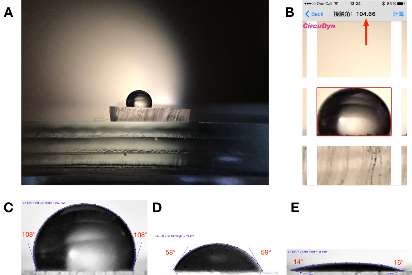
  5. Measure the contact angle of the drop in the image e.g. using ImageJ [2] software with a plugin for contact angle measurements [3] or get a rough estimate using an app on your smartphone.[4]

Contact angle measurements of water on PDMS: (A) Raw image from iPhone 6S front-facing camera with PDMS-lens. (B) Direct measurement using app on smartphone (based on θ/2 calculation) (C-E) ImageJ measurements using DropSnake plugin. Unmodified PDMS (C) and PDMS treated with oxygen plasma with increasing intensity (D-E).


What else should I know?

The focal length of the PDMS-lens is determined by the volume of PDMS used as described by Lee et al. [5]. However, it is difficult to control the volume of PDMS using a pipette due to the high viscosity of PDMS. We recommend making a range of lens sizes and testing them on your smartphone camera to see which gives the right focal length. If your digital scale has milligram precision you can measure the amount of PDMS used for each lens. The mass of each PDMS-lens is typically less than 10 mg. You can decrease the focal length further by adding PDMS to an already cured lens. Modern smartphones have both a rear-facing and a front-facing camera and in our experience the drop focusing was easier when using the front facing camera. The images taken here were captured with an iPhone 6S from Apple using the front-facing camera with a 5MP sensor. The weight of the cured PDMS lens was 7 mg.

Tip: you can also remove the PDMS-lens from the cover slip and place it directly on your camera. Although, it might be more difficult to center.

Calculating contact angles from images of sessile drops can be done using a range of techniques.[6] If the drop volume is small and the contact angles are not extreme, we can generally neglect droplet distortion due to gravitational effects. Extrand and Moon [7] calculated that gravitational effects can be neglected for a water droplet sitting on a hydrophilic surface (θ=5°) if its volume is less than 5 μL and less than 2.7 μL on a hydrophobic surface (θ=160°). If we assume the drop to be spherical, the contact angle can be estimated by multiplying the angle between the base and the height of the droplet by 2. This is referred to as the θ/2-method and is implemented by e.g. the Contact Angle Measurement app [4] for iOS. Sessile drop measurements are generally limited by the experimental setup and operator error, but typically has a precision of ±3°.[8] Image-processing algorithms relying on curve fitting of the droplet outline can enhance reproducibility. ImageJ [2] with DropSnake-plugin [3] uses active contours (energy minimization) to track the outline of the drop and calculate contact angles. This increases precision, but is slower and currently requires analysis on a separate computer.

Acknowledgements

The Research Council of Norway is acknowledged for the support to the Norwegian Micro- and Nanofabrication Facility, NorFab (197411/V30).

References

  1. S. Bhattacharya, A. Datta, J. M. Berg and S. Gangopadhyay, J. Microelectromech. S., 2005 14, 590–597
  2. ImageJ software
  3. DropSnake ImageJ-plugin for contact angle measurements
  4. Contact Angle Measurement iOS app (Japanese)
  5. W. M. Lee, A. Upadhya, P. J. Reece, and T. G. Phan, Biomed. Opt. Express, 2014, 5, 1626–1635
  6. Y. Yuan and T. R. Lee, Surface Science Techniques, Springer, Berlin/Heidelberg, 2013, 51, 3–34.
  7. C. W. Extrand and S. I. Moon, Langmuir, 2010, 26, 11815–11822.
  8. A.F. Stalder, G. Kulik, D. Sage, L. Barbieri and P. Hoffmann, Colloids and Surfaces A: Physicochem. Eng. Aspects, 2006, 286, 92–103.
Digg This
Reddit This
Stumble Now!
Share on Facebook
Bookmark this on Delicious
Share on LinkedIn
Bookmark this on Technorati
Post on Twitter
Google Buzz (aka. Google Reader)

Universal and Multi-material Bonding Method for Rapid and Low-cost Assembly of Microfluidic Devices

Ya-Yu Chiang, Nikolay Dimov, Nicolas Szita

Department of Biochemical Engineering, University College London, London, United Kingdom

E-mail: n.szita@ucl.ac.uk


Why is this useful?

The packaging of micro-systems relies strongly on the capability to bond different types of materials reliably whilst maintaining the microstructures and their dimensions. However, the bonding of different materials each with their specific physical and chemical properties frequently turns into a tedious, thus time consuming operation; often, the choice of materials and microfabrication techniques are limited by the bonding technique. Particularly challenging for bonding can be combinations of quartz, glass or silicon with polymers and metals.

Here we demonstrate a rapid, low-cost, UV-irradiation based bonding method, which is suitable for the bonding and assembly of quartz-to-silicon, quartz-to-metal, quartz-to-polymer, quartz-to-quartz devices.  We demonstrate in detail on the more challenging combinations, namely the bonding of a quartz slide to an aluminum sheet. In our example, the aluminum sheet contains the microfabricated structure. The same procedure is applicable for the other material combinations, i.e. quartz-to-silicon, quartz-to-polymer, quartz-to-quartz or quartz-to-metal for a metal other than aluminium; the main requirement for implementing our method is that at least one material is transparent to UV light.


What do I need?

  • Aluminum sheets, thickness of 1 mm (e.g. AW6082-T6, Smiths Metal Centres, UK)
  • Micro milling machine (e.g. CNC MicroMill GT, Minitech, US)
  • Flat head end-mills 0.25 mm, and 2 mm (e.g. PMT Endmill, US)
  • Plasma Cleaner (e.g. PDC-32G-2, Harrick Plasma, UK)
  • UV-curing adhesive (e.g. NOA 61, Noland Products, UK)
  • UV lamp, 100 W, 365 nm (e.g. B-100 AP, UVP, Cambridge, UK)
  • Quartz microscope slide, fused quartz, 25.4 × 76.2 x 1 mm3 (e.g. 42297, Alfa Aesar, UK)


What do I do?

1. Device design and leveling of the metal substrate

  • Draw your device design in any available computer aided design (CAD) software. As the surface roughness of the metal substrate can vary, a polishing step is recommended prior to the actual fabrication.
  • Generate the G-code for the CNC machine using any CAM/CAD software. Two separate files are required: one for the polishing of the substrate, and one for the actual design.

2. Micro milling

  • Clamp the aluminum substrate on the table of the milling device. Make sure that you do not bend the material.
  • Set the initial coordinates (X0, Y0, Z0) for this work.
  • Polish the aluminum substrate with 2 mm flat head end-mill.
  • Change to the smaller diameter tool (0.25 mm).
  • Mill the designed structure in the aluminum sheet with the 0.25 mm end-mill.

3.  Cleaning the aluminum substrate from residues.  Dust is removed first with water, and then the surface is cleaned  first with ethanol, and then with compressed air. Finally the substrate is dried in an oven (120ᴼC, 30 min).

4. Plasma activation of the quartz microscope slide. Place the quartz microscope slide inside the Plasma Cleaner. The plasma treatment is a ‘surface process’, therefore the surface that is about to be bonded should be facing towards the center of the chamber.

  • Evacuate the chamber until a working pressure of 500 mTorr at a constant inflow of air is established.
  • Switch the plasma on at 27 W, which is the highest intensity available for the specified Plasma Cleaner.
  • ‘Turn off’ the plasma after 90 seconds.
  • Vent the chamber of the Plasma Cleaner by opening the needle valve and allowing air to enter through the flow meter.
  • Remove the activated piece of substrate from the Plasma Cleaner.

5. Bonding

  • Align the substrates (and thus enclose the micro fabricated structures) by firmly pressing the activated quartz surface to the aluminum sheet. A fine interfacial gap is forming between the quartz and aluminum surfaces.
  • In case you have a large chip or thin fragile substrates you may need to carefully clamp the substrates together.
  • Prime the gap with the adhesive while holding the two substrates of your device together. In order to do so, place a small drop of adhesive to one edge, i.e. to the gap between the two substrates. The adhesive will flow into the gap due to capillary action. Thick substrates will be held together sufficiently by the adhesive film. The flow of the adhesive will stop at the edge of the microfabricated structures as a results of surface effects (surface tension and wetting angle). Inspect whether the device is completely filled with the adhesive. Add more of the adhesive if necessary.
  • Cure the completely primed device by exposing it to UV-light, 365nm @ 100 W for 5 to 10 minutes.
  • Place the device into the oven at 50°C. According to the supplier’s specifications, the bond reaches its maximum strength after 12 hours at 50°C. Alternatively, for temperature-sensitive materials, longer incubation times at room temperature are also feasible.

The main advantages of the presented bonding method are as follows:

1. Hybrid microfluidic devices can be easily bonded.

2. The method is relatively simple and does not require clean-room conditions.

3. The method works with any UV transparent material as long as the surfaces are clean, smooth and as long as they can promote the capillary action necessary for the priming with adhesive.

4. It is an economic bonding method. An expected 30 mL of UV-curing adhesive should be enough for the bonding of over hundred microfluidic devices. Each assembly will thus cost less than £0.2 GBP (or approximately $0.3 USD).


What else should I know?

Q1. What processes do you use to create the holes in the quartz slide?

A1. The quartz slides are drilled with diamond drill bit (Eternal tools, UK), 1 mm in diameter, and a bench drill (D-54518, Proxxon , Germany) at 1080 rpm.  This is a slow operation as the process is closer to grinding rather than drilling. To avoid crack formations in the quartz slide and to cool diamond bit a droplet of water is applied on the surface of the quartz. After each cycle grinded quartz debris may be accumulating at the bottom of the hole; it can be removed by using a pipette and cooling liquid.

Q2. Have you ever tried this method with channel geometries that are disconnected? For example, a channel  layout shaped like an “O” that would prevent adhesive wetting from the edge of the slide?

A2. We had bonded successfully channels with complex, serpent geometries. For “O”-shaped channels we use additional feed, a hole, drilled in one of the substrates that allows the adhesive to spread.

Q3. Does the adhesive ever “burst” and enter the channels? If so, what methods do you use to minimize the chances of this happening?

A3. Yes, it happens occasionally that the adhesive fills the channel.

To prevent this: minimum amount of glue is applied at a time, and also the propagation of the front needs to be monitored. We wait until the glue reaches the channel edge, and then we place the assembly under the UV-light for curing.

If the channel is filled with small amount of adhesive, the glue could be washed out with a bit of ethanol or acetone.

Completely filled channel requires disassembly, cleaning with acetone or ethanol of the substrates. Afterwards, the procedure can be repeated with less glue.

Digg This
Reddit This
Stumble Now!
Share on Facebook
Bookmark this on Delicious
Share on LinkedIn
Bookmark this on Technorati
Post on Twitter
Google Buzz (aka. Google Reader)

Highly precise alignment for the rapid fabrication of Plexiglas® microfluidic devices

G. Simone

University of Naples Federico II, Piazzale Tecchio 80, 80125 Napoli, Italy.


Why is this useful?

Most of microfluidic devices use channels with rectangular cross-sections. The microfabrication of rectangular shaped channels is straightforward with standard tools such as photolithography.

Fluid dynamics, rheology, soft matter and, recently, biology-based investigations need circular cross-section microchannels; indeed, pre-fabricated capillaries are normally used to carry out the studies. However, capillaries are impractical for some investigations requiring complicated designs.

For Plexiglas® (or other plastic) devices, microfabrication by micromilling is a low cost procedure, which, in the last decades, has gained popularity in the field of microfluidic applications.1-2 The fabrication and the sealing of Plexiglas® microchannels with circular cross-section can be challenging.

Here, a method of fabrication of plastic microfluidic devices with circular cross-section is presented. The method is low cost and it can be performed by minimally trained users. The alignment step builds on a procedure first introduced by Lu et al. that used circular magnets to align layers of polydimethylsiloxane (PDMS).3 The protocol is validated for circular cross-section channels, but it can be used for fabricating rectangular channels or special inlets as well.


What do I need?

  • Plexiglas® sheets (thickness 1mm) Rohm Italy
  • CNC MicroMill (Minitech, US)
  • Ball nose end-mills (0.001 inch, PMT Endmill)
  • Magnets 4 mm × 4 mm× 4 mm, DX
  • Microscope Bresser 58-02520
  • Clamps RS Italy
  • Ethanol
  • Microscope (or stereomicroscope)
  • Glass slides for microscopy (50 mm × 75 mm)


What do I do?

1. Computer aided design of the device (CAD).

  • Design the microfluidic channels with CAD software. Fig. 1a displays the top and bottom layer of the main channel and, in particular, aligned square through-holes in each layer.
  • Translate the CAD file to Computer Numerical Control (CNC) code for micromilling.

2. Micromilling

  • The endmill should be aligned to set the point z=0 by using a microscope.
  • Then, the microchannels (top and bottom) must be milled. Channel with depends on the endmill diameter.4 It is worth emphasizing that setting the correct work parameters (such as tool speed and depth) is crucial. Indeed, if the latter are not appropriate, the plastic workpiece develops internal stresses that during the bonding result in cracks and chip breakdown.
  • Finally, the through holes and the frame have to be milled. The number of through holes for locating the magnets depends on the dimension of the microfluidic device. It is good practice for the rectangular through-holes to have a pitch of roughly 10 mm (this dimension depends on the size of the microchannels and of the magnets).

3. Alignment

  • Align the top and bottom layers with a stereomicroscope (Fig. 1b). The bottom layer should be set on a solid surface and the magnets inserted into the through-holes. Then, the second layer should be placed on the first and a second set of magnets inserted in the square through-holes of the second layer.
  • The magnets located in the first and second layer naturally provide a good “first alignment” of the microchannels, while leaving freedom to slightly adjust the layers (i.e., this is a reversible sealing). Once the magnets are fixed, the quality of the alignment should be checked with a microscope.

    Fig. 1. The Fabrication. a. CAD design of a microfluidic channel with circular cross section. The length of the microfluidic device is 40mm, the width is 15mm. The depth of grooves is 50μm, width 25μm. b. Magnets employed for the bonding. C. Clamps used for sealing the microchannel.

4. Bonding

  • Clamp the Plexiglas® layers together and submerge assembly in ethanol for 15 minutes (Fig. 1c). For optimal bonding, the clamping should be done with clamps positioned at the edges of the Plexiglas®.5
  • After 15 minutes, the sealing of the microfluidic channels should be checked. If the Plexiglas® is sufficiently bonded, the magnets can be removed and glass slides placed on either side of the Plexiglas® layers. Clamp the glass slides and allow the assembly to rest for another 5-15 minutes.
  • The device is ready to be used for different applications as shown in Fig. 2a. Capillary tubing can be easily connected to the channel for modular design (Fig. 2b).

    Fig. 2. Examples of microfluidic devices. a. Perfusion of the samples through hole at the inlet. b. Perfusion through capillaries.

In conclusion, analyzing the protocol, the following advantages can be emphasized:

  1. The process is designed for different materials, but it fits perfectly with Plexiglas®
  2. The equipment necessary for the fabrication and assembly includes simply a micromilling machine and a (stereo)microscope
  3. The use of square magnets (instead of circular ones) allows for more precise alignment due to further restriction to the sliding of the top and bottom layers.


References

  1. G. Simone, G. Perozziello, J. Nanosc. Nanotech., 2010, 11, 2057.
  2. G. Simone, RSC Advances, 2015, 5, 56848.
  3. J-C Lu, W-H Liao, Y-C Tung, J. Micromech. Microeng. 2012, 22, 075006-075014.
  4. G. Perozziello, G. Simone, P. Candeloro, F. Gentile, et al. Micro and Nanosystems, 2010, 2, 227-238.
  5. G. Medoro, G. Perozziello, A. Calanca, G. Simone, N. Manaresi, 2010, US Patent App. 13/257,545.

Digg This
Reddit This
Stumble Now!
Share on Facebook
Bookmark this on Delicious
Share on LinkedIn
Bookmark this on Technorati
Post on Twitter
Google Buzz (aka. Google Reader)