Author Archive

Degassing a PDMS mixture without a vacuum desiccator or a laboratory centrifuge and curing the PDMS chip in an ordinary kitchen oven

Aung K. Soe and Professor Saeid Nahavandi
Centre for Intelligent Systems Research, Deakin University, Australia

Why is this useful?


Whitesides (2001) advocated that soft lithography can facilitate researchers to fabricate PDMS lab-on-a-chip devices with accessible and affordable resources [1]. A typical soft lithography fabrication laboratory requires master reverse molds, a PDMS pre-polymer mixer, scales for weighing, a vacuum desiccator, an oven and oxygen plasma treatment of PDMS surfaces to become hydrophilic [2].

In soft lithography, the PDMS elastomer is first mixed with the cross-linker (curing agent) in a weight ratio of 10:1. Stirring the mixture forms air bubbles. Traditional soft lithography protocols recommend using a vacuum desiccator before pouring the mixture onto the mold master. The PDMS pre-polymer is cured fully or partially inside the oven at 80 to 95 °C for 15 to 20 minutes, transforming the resin into solid silicone rubber. However, not all researchers who need to fabricate PDMS chips have all the resources stated.

LaFratta (2010) demonstrated that a laboratory centrifuge can be used to degas PDMS [3], but a desktop laboratory centrifuge (to degas) and an oven (to cure) may not be accessible or affordable to all researchers. The technique described here uses a handheld electric mixer to mix and degas the PDMS pre-polymer. An ordinary kitchen oven is used to cure the PDMS chip.

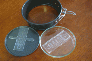
Since the food processor cannot be used for more than 3 minutes, the procedure is done in 2 sections, each lasting 2.5 minutes with 1 minute period between them. A Pyrex® petri dish is used to hold the reverse mold (master), so the dish will not deform inside the oven. The oven must be switched on and off so that the Pyrex does not crack.

What do I need?


  • SYLGARD 184 silicone elastomer base and curing agent (Dow Corning)
  • a low-cost hand-held electric mixer
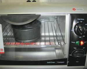
  • a kitchen grill oven with sustained heating capacity at 80 °C
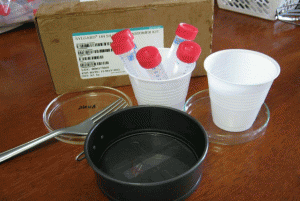
  • a baking cup (or a Pyrex petri dish) and polystyrene petri dishes for PDMS chip storage
  • a polished micro-machined or patterned reverse master mold that will not float on the PDMS pre-polymer
  • a scale that can work in units of grams
  • consumables: gloves, disposable cups, 2 or 4 plastic centrifuge tubes (15 ml capacity)

How do I do it?


1. Weigh the PDMS base and curing agent in the desired ratio in a disposable cup. 10:1 is the most common ratio, but any ratio can be used depending on the desired stiffness of the cured polymer.
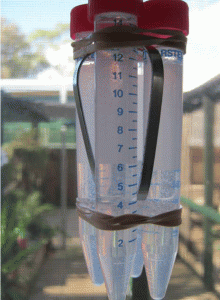
2. Mix base and curing agent together with the stirrer attachment of the hand-held electric mixer. Pour the pre-polymer evenly into 2 or 4 centrifuge tubes. If there is not enough pre-polymer for 2 or 4 tubes, fill 1 or 3 tubes and one more tube with water for balancing. It is important to balance the attachment during spinning. Tightly seal the centrifuge tube caps.
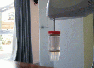
3. Tie the tubes to the stirrer attachments of the handheld mixer. Hold the mixer in a vertical position, switch on and spin for 2.5 minutes, then stop to give the spinner a rest for 1 minute. Turn the bottles 180 degrees and spin for another 2.5 minutes until all the bubbles have escaped from the pre-polymer mixture.
4. Pour the centrifuged PDMS onto the patterned reverse master mold in the baking cup or Pyrex petri dish.
5. Put the master mold container in the oven and cure at 80°C for 10 minutes if the baking cup is used. If the Pyrex petri dishes are used, the heat must be switched on for 5 minutes then off for 5 minutes since Pyrex dishes can crack under continuous heat. Switch the heat on and off for 30 minutes.
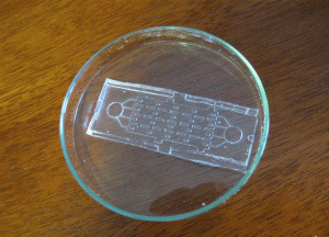
6. Peel the PDMS slab off the master using a sharp-tipped knife and store the PDMS chip in a polystyrene dish before autoclaving or treating with oxygen plasma.

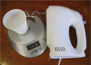
Figure 1. Weighing, mixing and stirring

Figure 2. Before spinning

Figure 3. Spinning the tubes attached to the processor

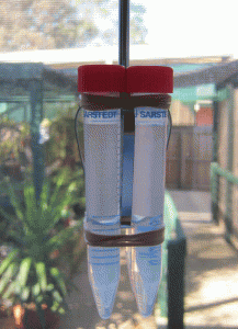
Figure 4. After spinning

Figure 5. Acrylic reverse mold in the baking cup

Figure 6. Baking cup in ordinary kitchen oven at 80 °C

Figure 7. Peeling off PDMS slab from the baking cup

Figure 8. Storing the PDMS chip inside a petri dish


What else should I know?


The reverse master can be fabricated in microfluidics fabrication foundries at Stanford University or California Institute of Technology. Reverse masters can also be made by machining pcrylic (also known as PMMA and plexiglass) with subtractive CNC machines such as the Roland DG MDX 40. Three-dimensional additive printers can also be used. Third-party service companies can also do micro-machining and surface polishing if one wishes to outsource the master fabrication task.

References


[1] G. Whitesides et al., Soft lithography in biology and biochemistry, Annu. Rev. Biomed. Eng., 2001, 3(1), 335-373.
[2] A. Harsch et al., Pulsed plasma deposition of allylamine on polysiloxane: a stable surface for neuronal cell adhesion, J. Neurosci. Methods, 2000, 98(2), 135-144.
[3] C. N. LaFratta, Degas PDMS in two minutes, Chips & Tips (Lab on a Chip), 17 August 2010.

Digg This
Reddit This
Stumble Now!
Share on Facebook
Bookmark this on Delicious
Share on LinkedIn
Bookmark this on Technorati
Post on Twitter
Google Buzz (aka. Google Reader)

DMF Flip-Chips: an easy route to digital microfluidics

Steve C.C. Shih1, 2 and  Aaron R. Wheeler1, 2, 3
1 Institute for Biomaterials and Biomedical Engineering, University of Toronto, 164 College St., Toronto, ON, M5S 3G9
2 Donnelly Centre for Cellular and Biomolecular Research, 160 College St., Toronto, ON, M5S 3E1
3 Department of Chemistry, University of Toronto, 80 St George St., Toronto, ON, M5S 3H6

Why is this useful?


Digital microfluidics (DMF) is a technique in which discrete droplets are manipulated by applying electrical fields to an array of electrodes.1 An advantage of DMF is that droplets serve as discrete microvessels in which reactions can be carried out without cross-talk between samples or reagents. In contrast to the more conventional geometry of enclosed microchannels, each sample on a DMF device can be addressed individually, and reagents can be dispensed from reservoirs, moved, merged and split.2
A key component in a functioning DMF device is the insulating layer (i.e., a dielectric material) which is deposited on top of the actuation electrodes to facilitate the build-up of charge which drives droplet actuation.3 Fabrication of dielectric layers can be time-consuming and the costs for depositing them can be very expensive (e.g., a common method is chemical vapour deposition of parylene C).  Alternative methods have been described,4 but in all previous work, a separate dielectric layer must be positioned onto a device.

Here, we report a new method which we have called “DMF Flip-Chips,” in which the device substrate itself serves as the dielectric layer. In this method, actuation electrodes are patterned on one side of a glass coverslip (or other thin substrate), which is then flipped over such that the substrate serves as the insulating layer for droplet manipulation. This method is faster than conventional fabrication, and we speculate it will be useful for laboratories that do not have a dielectric coater but would like to use digital microfluidics.

What do I need?


  • Glass coverslips with thickness of 160 mu.gifm or less
  • Indium-tin-oxide coated glass (Delta Technologies Ltd, Stillwater, MN) to serve as top substrate
  • Scissors
  • Double-sided tape
  • Teflon-AF

How do I do it?


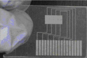
1. Pattern a glass coverslip with an array of electrodes. This can be accomplished using conventional cleanroom techniques2,3 or by rapid prototyping techniques such as microcontact printing,5 laser toner printing,6 or marker masking.7

Figure 1

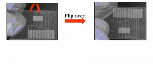
2. Flip the substrate over and coat the “bottom” (now top) with Teflon-AF as described previously. Likewise, coat an ITO-glass substrate with Teflon-AF.2,3

Figure 2

3. Assemble the device with the patterned glass substrate on the bottom, double-sided tape spacers in the middle, and ITO-glass substrate on the top. Sandwich droplets between the two substrates.
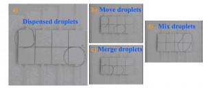
4. Apply driving potentials (~500 VRMS and 15 kHz) between electrodes on the bottom and top plates, which causes droplets to a) dispense, b) move, c) merge, and d) mix as shown.

Figure 3

What else should I know?


  • Potentials of ~500 VRMS  are appropriate for bottom plates formed from a 160 mu.gifm coverslip.  Lower potentials can be used with thinner coverslips.
  • Additionally, lower voltages can be used for substrates formed from materials with higher dielectric constants than glass.
  • Clean surfaces with methanol or water after every use.
  • Thinner cover slips are difficult to use because they are very brittle and fragile.

Acknowledgements


We thank Irena Barbulovic-Nad for helpful discussions.

References


[1] A. R. Wheeler, Science, 2008, 322, 539-540.
[2] S. K. Cho, H. J. Moon and C. J. Kim, Journal of Microelectromechanical Systems, 2003, 12, 70-80.
[3] M. G. Pollack, A. D. Shenderov and R. B. Fair, Lab Chip, 2002, 2, 96-101.
[4] M. J. Jebrail, N. Lafreniere, H. Yang and A. R. Wheeler,  A two-for-one dielectric and hydrophobic layer for digital microfluidics, Chips & Tips (Lab on a Chip), 6 July 2010.
[5] M. W. Watson, M. Abdelgawad, G. Ye, N. Yonson, J. Trottier and A. R. Wheeler, Anal. Chem., 2006, 78, 7877-7885.
[6] M. Abdelgawad and A. R. Wheeler, Adv. Mat., 2007, 19, 133-137.
[7] M. Abdelgawad and A. R. Wheeler, Microfluid. Nanofluid., 2008, 4, 349-355.

Digg This
Reddit This
Stumble Now!
Share on Facebook
Bookmark this on Delicious
Share on LinkedIn
Bookmark this on Technorati
Post on Twitter
Google Buzz (aka. Google Reader)

Rapid, inexpensive and stress free drilling in glass substrates or thermally bonded glass chips using electrochemical spark erosion method

Arun Arora
KIST Europe, Korea Institute of Science and Technology, Campus E7.1, 66123 Saarbrücken, Germany

Background


An electrochemical spark erosion method is presented to drill holes in glass substrates or thermally bonded glass chips. Shohi and co-workers [1] reported this method in 1990. We have modified the method by using  a Pt wire 0.5 mm diameter anode instead of a steel needle cathode as a drilling needle and 50 V (instead of 35 V) was applied from a variable unregulated dc power supply to produce a constant spark in 8 M sodium hydroxide solution. When a steel needle cathode was used as reported in reference Shohi’s method, a large amount of brown precipitate was formed, which entered into the channel and created blocks.
Figure 1 shows a schematic diagram of the complete process and Figure 2 is a photo of the setup showing the process in operation.

Figure 1: Electro chemical spark erosion method of drilling holes in a thermally bonded glass device
Figure 2: Photo of the electro chemical spark erosion method for drilling holes in a thermally bonded glass device

The conventional methods to drill holes in glass include laser ablation or powder blasting. Both methods require expensive setup and trained staff therefore these methods are expensive.  The dentist drill also used to drill holes in bonded glass devices which can cause stress to the glass or can damage the channel walls. Sometimes glass particles can also clog the channel. A simple method for drilling access hole in a glass substrate or a thermally bonded glass chip is presented.

What do I need?


  • Pt wire (0.5 mm diameter)
  • Sodium Hydroxide solution (8M) (Caution)
  • Variable DC Power supply (100 V)
  • Petri dish

What do I do?


  1. Fixed a pt wire cathode on the side of the Petri dish as shown in schematic diagram in figure 1 or the photo in figure 2. Make sure that Pt wire reaches to the bottom of the petridish so it can make contact to the sodium hydroxide solution.
  2. Wear gloves and safety goggles and then place the Petri dish on a dry table. Fill it with sodium hydroxide (8M) solution (Caution: sodium hydroxide solution can cause severe burn if it comes in contact with skin. If any part of the body comes in contact, immediately wash it off with plenty of water.)
  3. Mark the position for the hole using a glass marker pencil on other side of the glass substrate where you want to drill the hole. Place it in the Petri dish facing the mark downward and immersed it approximately 5 mm deep into the sodium hydroxide solution.
  4. Connect the PVC covered anode and Pt wire cathode to the DC power supply.
  5. Hold the PVC covered Pt electrode precisely over the marked position on the glass substrate. Switch the power supply on and increase the voltage until the orange spark become visible. After 5 to 10 seconds of constant spark check the progress of drilling by taking out the glass substrate and viewing it with a hand held magnifying lens or a microscope (Figure 3).

Figure 3
Figure 3: Photo of the hole drilled by electrochemical spark erosion; a) Hole across a 60 µm wide channel. b) a 500 µm diameter hole across a 60 µm wide channel in a pre-bonded capillary electrophoresis glass device

References


[1] Shohi, S.; Esashi, M. Photoetching and Electrochemical Discharge Drilling of Pyrex Glass, Technical Digest of the 9th Sensor Symposium, Japan, 1990, 27.

Digg This
Reddit This
Stumble Now!
Share on Facebook
Bookmark this on Delicious
Share on LinkedIn
Bookmark this on Technorati
Post on Twitter
Google Buzz (aka. Google Reader)

A simple technique for feeding constant rate of flow

Piotr M. Korczyk [1,2], Olgierd Cybulski [1], Sylwia Makulska [1] and Piotr Garstecki [1]
[1] Institute of Physical Chemistry, Polish Academy of Sciences, Kasprzaka 44/52, 01-224 Warsaw, Poland
[2] Institute of Fundamental Technological Research, PAS, Pawinskiego 5B, 02-106 Warsaw, Poland

Why is this useful?


Syringe pumps are known to generate fluctuation of rate of flow (1). In some applications the impact of these oscillations can be relevant. We demonstrate and characterize in detail a simple method for feeding fluids into microfluidic devices at a constant rate of flow. This simple experimental setup provides for more precise control and for better stability of the rate of flow than the commonly used syringe pumps.

What do I need?


  • Source of pressurized gas
  • Tubing for pressurised gas
  • Pressure regulator
  • Pressure transducer
  • Container for pressurized liquid
  • Polyethylene tubing
  • Steel capillaries
  • Tygon tubing
  • Needles

How do I do it?


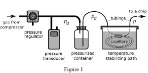
1. Connect pressure source with pressure regulator via tubing and then with the pressurized container filled with carried liquid (Fig. 1).

2. Place pressure transducer between the regulator and the container (Fig. 1).

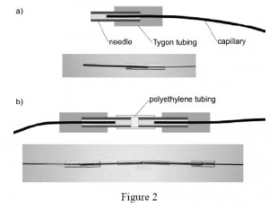
3. For connections between the polyethylene tubing and the steel capillaries use short sections of the Tygon tubing. In order to avoid obstruction of the terminus of the capillary by the elastic Tygon, first put a blunted needle all the way through the Tygon tubing. Then insert the terminus of the capillary into the needle, and partially withdraw the needle from the Tygon to let it squeeze around the capillary and seal the connection (Fig. 2).

4. Connect the end of the capillary with the pressurised container for liquid via a polyethylene tubing and the other end of the capillary with the chip (Fig. 1).
5. Place the resistive capillary into a temperature stabilizing bath of liquid (e.g. water) to avoid temperature fluctuations which can affect viscosity of the liquid guided through the capillary and its hydraulic resistance to flow (Fig. 1).

What else should I know?


Using the resistive capillaries for delivering stable rates of flow requires calibration of the hydraulic resistance of the capillary. First estimate the Reynolds number for the flow on the basis of the dimensions of the capillary and the range of required rates of flow. If the flow is laminar, the relation between the pressure P applied to the container with liquid and the rate of flow Q through the capillary is linear: P=RQ  where R is the hydrodynamic resistance. In order to calibrate for R place the capillary in the bath and apply a known pressure to the container. Then evaluate the rate of flow by measuring the rate of change of mass on an analytical balance collecting the liquid flowing out from the capillary.

The ratio of P/Q yields R. Alternatively, for more precise calibration collect a number of values of Q for different values of P and fit a line: P = RQ  to retrieve R.

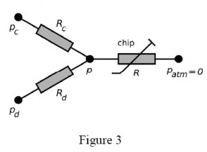
Figure 3 presents example of the equivalent electric circuit of the system that draws a continuous liquid (under pressure pc and a to-be-dispersed fluid (pd) from pressurized containers to form droplets on a microfluidic chip. The capillaries have hydrodynamic resistances Rc, Rd, the pressure at the droplet generator is p. The droplets flow through a channel of resistance R (varying, due to the generation and motion of droplets) up to the outlet (pressure 0, since all pressures are relative to the atmospheric pressure).

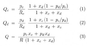
In general, having capillaries of known resistance (e.g. already calibrated for a desired liquid), one may easily calculate the rates of flow of the continuous phase (Qc) and of the droplet phase (Qd) from Ohm and Kirchhoff circuit laws:

where  xc = R/Rc and xd = R/Rd.

It should be noted that although Qc and Qd are not mutually independent functions of respective pressures pc and pd, the cross-dependency becomes irrelevant for small values of xc and xd i.e. when the resistance of the capillaries is much larger than the resistance of the chip. Keeping Rc >> R and Rd >> R also minimized the variation of Qc and Qd in response to the variation of R. It is practical to to have pc and pd of similar magnitude, hence for a given range of rates of flow the user should tailor resistance of capillaries to meet the following condition: Rc / Rd ≈ Qd /Qc.

References


(1) R. Green and S.A. Vanapalli, Quick assessment of the stability of flow generated by a syringe pump in a microfluidic device, Chips & Tips (Lab on a Chip), 16 July 2009.

(2) P. Korczyk, O. Cybulski, S. Makulska, P. Garstecki, Effects of unsteadiness of the rates of flow on the dynamics of formation of droplets in microfluidic systemsLab Chip, DOI:10.1039/C0LC00088D.

Digg This
Reddit This
Stumble Now!
Share on Facebook
Bookmark this on Delicious
Share on LinkedIn
Bookmark this on Technorati
Post on Twitter
Google Buzz (aka. Google Reader)

Degas PDMS in two minutes

Christopher N. LaFratta
Department of Chemistry, Tufts University, Medford MA, USA

Why is this useful?


Mixing the base and curing agent of PDMS inevitably incorporates air bubbles into the prepolymer.  These bubbles are usually removed after casting by degassing the sample under vacuum.  Vacuum degassing works well but requires about 30 minutes or more depending on the vacuum and amount of gas stirred in.  The technique described here uses a typical laboratory centrifuge to degas PDMS in two minutes.  The centrifuged PDMS will yield a bubble-free solid silicone rubber when cast on a smooth surface.

What do I need?


  • SYLGARD 184 silicone elastomer base & curing agent (Dow Corning)
  • 2 Centrifuge tubes (15 mL)
  • Clay Adams II compact centrifuge (3200 rpm or 1315 × g relative centrifugal force)

How do I do it?


  1. Weigh the PDMS base and curing agent (10:1) in a disposable centrifuge tube.
  2. Mix base and curing agent together with a wooden stick.
  3. Balance centrifuge with 2nd tube containing comparable amount of PDMS or water.  Place in centrifuge for 2 min.
  4. Cast centrifuged PDMS onto patterned wafer.
  5. Oven cure at 75°C for 1 h.

What else should I know?


If the PDMS is cast over high aspect ratio features, such as tall SU-8 photoresist lines, air bubbles may get folded in as the liquid PDMS flows over crevices.  These small isolated bubbles can usually be degassed under vacuum in about one minute.

A) Mixed PDMS in a centrifuge tube, note the air bubbles that have been mixed in. B) PDMS being degassed by centrifugation. C) Degassed PDMS after 2 minutes of centrifuging without any air bubbles.

Casting PDMS on a patterned silicon wafer

Cured PDMS cut from silicon wafer mold without air bubbles.

References


[1] C. N. LaFratta, T. Baldacchini, R. A. Farrer, J.T. Fourkas, M. C. Teich, B. E. A. Saleh, M. J. Naughton J. Phys. Chem. B, 2004, 108, 11256-11258.

Digg This
Reddit This
Stumble Now!
Share on Facebook
Bookmark this on Delicious
Share on LinkedIn
Bookmark this on Technorati
Post on Twitter
Google Buzz (aka. Google Reader)

A method for periodic sterile sample collection during continuous cell culture in microfluidic devices

Dmitry A. Markov,1,2 Elizabeth M. Lillie,1,2 Philip C. Samson,2,3 John P. Wikswo,1,2,3,4 Lisa J. McCawley2,5
1 Department of Biomedical Engineering, Vanderbilt University, Nashville, TN
2 Vanderbilt Institute for Integrative Biosystems Research and Education (VIIBRE), Vanderbilt University, Nashville, TN
3 Department of Physics and Astronomy, Vanderbilt University, Nashville, TN
4 Department of Molecular Physiology and Biophysics, Vanderbilt University Medical Center, Nashville, TN
5 Department of Cancer Biology, Vanderbilt University Medical Center, Nashville, TN

Why is this useful?


Allows for sterile sample collection during long-term slow perfusion experiments. Current developments in microfluidic devices and their applications in biology during long-term cell and tissue culture have introduced additional challenges associated with periodic sterile collections of effluent for storage and further analysis. Pumps (either mechanical or electroosmotic) and gravity-fed systems work well for delivering media at very slow flow rates (< 1 µL/min). However, sample collection at these rates becomes a non-trivial task, especially when one-, two-, or three-week-long experiments are required. For example, it would take 24 hours to collect 1 mL of effluent at a flow of 0.7µL/min. Two important parameters to consider are sample evaporation during the collection step and sterility maintenance during multiple periodic collections. These are especially critical for the gravity-fed systems where the output port of the cell culture device has to be opened to the atmospheric pressure. To overcome these challenges, we have tested use of Breathe-Easy gas permeable adhesive membranes from Electron Microscopy Sciences (cat. # 70536-10) as aseptic filters on top of sample collection vials. These membranes are inexpensive, easy to use, and gas permeable, allowing for unimpeded fluid flow into the sample collection reservoir, while maintaining sterility of the whole system during sample collection. During our three-week-long cell culture experiments, we were able to perform multiple 24-hour effluent collections from our bioreactor with a 5-day period while maintaining sterility of the whole system. Upchurch valves were used to switch the flow between the waste reservoir (4 days) and the sample collection vials (1 day). The evaporation was reduced by keeping the complete system at 100% humidity within a CO2 cell culture incubator.

What do I need?


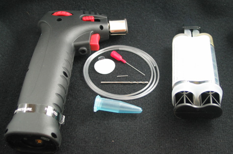
  • 1.5 mL microcentrifuge tube
  • Butane torch or Bunsen burner
  • Small 25 gauge heated needle for puncturing
  • Short piece of small 23 gauge stainless steel tubing to be inserted into the microcentrifuge tube
  • 90 second epoxy (Araldite 2043 or similar)
  • Small bore Tygon tubing (OD = 1/16th “, ID=0.020”)
  • Drill bit #53
  • Breathe-Easy membrane (Electron Microscopy Sciences, cat. # 70536-10)

How do I do it?


Tube insertion using stainless steel interface connector:

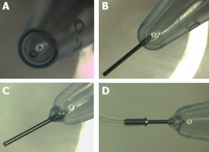
  • Heat the puncturing needle with a cigarette lighter, Bunsen burner, or a small butane torch and carefully make a hole at the bottom of the microcentrifuge tube.
  • Use a 4-6 mm long piece of small gauge stainless steel interface tubing, and insert it into the punctured hole.  Outer diameter of this tubing should be larger by 1 or 2 gauges than the puncturing needle (23 ga. tubing has larger diameter than 25 ga. tubing). The fit should be snug.
  • Apply a small bead of 90 second curing epoxy to affix the interface tube to the microcentrifuge tube.
  • After the epoxy dries, feed tygon tubing onto the stainless steel interface tube.
  • In our case, we used a 25 ga needle to create a hole and a 23 ga stainless steel tubing (OD=0.022″) as an interface between a 1.5 ml microcentrifuge tube and flexible Tygon tubing (OD=1/16th, ID=0.020″).

Alternative procedure for direct flexible tube insertion:

  • Drill a small hole in the bottom of the microcentrifuge tube
  • Insert the Tygon tube and apply 90 second epoxy to glue the two parts together.
  • We used a #53 drill bit (Ø = 0.0595″) for 1/16th OD tygon tubing.

To apply the filter:
The following procedure should be performed wearing gloves and under aseptic conditions.  Biosafety cabinets or laminar flow hoods with proper filtration are adequate.  The Breathe-Easy membranes typically come sterile from the supplier and should be opened inside the biosafety hood and handled with sterile tweezers.  The modified microcentrifuge tube with attached Tygon tubing can be sterilized using common procedures involving autoclave, alcohol, or gamma radiation sterilization (gas sterilization was not tested). All mentioned approaches performed reasonably well and were quite adequate; however, we have found that multiple autoclave sterilization cycles often softened the epoxied connections and alcohol sterilization required excessive handling of the components.  In our opinion, gamma ray sterilization was found to be the easiest, simplest, and the most convenient approach.

  • Start with sterile membrane and microcentrifuge tube with proper tubing attached.
  • Cut off the snap lid of the microcentrifuge tube.
  • Peel one half of the protective film from one side of Breathe-Easy filter and attach exposed adhesive side of filter to the top rim of the tube.
  • Then, remove the second half of the protective film and fully attach filter (make certain the seal is good around the perimeter with firm pressure applied with flat edge of forceps).
  • When ready to use the assembly, carefully remove the top protective layer.

We used this method to periodically sample effluent from our bioreactor cartridges during long term cell culture.  Each cartridge contains 4 reactors that are connected to a single manifold shown in Figure 4D.

Figure 1. Tools and supplies needed

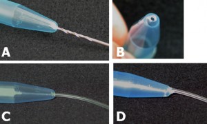
Figure 2. Preparing the microcentrifuge tube – Method 1. A) Hole punched with a hot needle. B) A piece of stainless steel needle inserted into the punctured hole. C) Inserted tube fixed in place with a 90 second epoxy. D) Flexible Tygon tubing attached to the interface tube.

Figure 3. Preparing the microcentrifuge tube – Method 2. A) Hole being drilled at the bottom. B) View of the drilled hole. C) Insertion of the small diameter Tygon tubing. D) Application of the 90 second epoxy to fix the inserted tube in place.

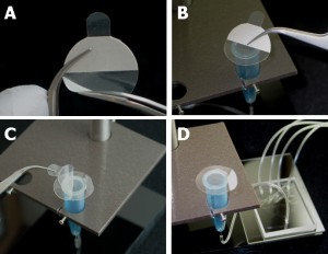
Figure 4. Preparation of the sterile cover. A) Protective plastic is removed from the adhesive side of the filter. B) Filter membrane is attached to the tube rim. C) Use caution to remove top protective plastic from the membrane attached to the tube. D) View of the tube with the filter mounted in the sample holder and attached to the collection network.

Acknowledgements


We would like to acknowledge support provided by the following grants: NIH/NCI R21 CA126728-01A1 and DOD/BCRP W81XWH-09-1-0444.

Digg This
Reddit This
Stumble Now!
Share on Facebook
Bookmark this on Delicious
Share on LinkedIn
Bookmark this on Technorati
Post on Twitter
Google Buzz (aka. Google Reader)

Wall plug inspired connectors for macro to microfluidic interfacing

Lorenzo Capretto1, Stefania Mazzitelli2, Stefano Focaroli2 and Claudio Nastruzzi2
1 School of Engineering Sciences, University of Southampton, UK
2 Department of Chemistry and Technology of Drugs, University of Perugia, Perugia, Italy

Why is this useful?


Common ways to link microdevices with standard fluidic equipments (such as syringe or peristaltic pumps) are based on the use of nanoports, created by: hand screwing a tube in the substrate material, gluing the tube fitting directly on the microfluidic device or commercial nanoports.
However, when such types of connection are used, there might be a series of potential issues, including: possible leakage of liquid from the connections, especially when high pressure inlet are required, possible clog of the port when glue is used or the high cost of the commercial devices.
Here, we demonstrate an easy and effective way for the creation of cheap and tight microfluidic connection ports for a varied range of substrate material including glass, silicon and polymers. Our approach solves the issues reported above with the creation of and inexpensive, well tight and glue-free port based on a “wall plug inspired” effect.

What do I need?


  • Plastic tube (ETEF, FEP or PTFE) 1/16″ OD, 0.75 mm ID [1]
  • 21 gauge hypodermic needle [2]
  • Drilling bit 1.5 mm [3]
  • A Proxxon, table top, micro miller [3] or any other handheld power tool
  • A cutting disc made of a hard abrasive [3] or any other tool for cutting the needle


Fig. 1.  Tubing used for the production of “wall plug inspired” connectors for macro to microfluidic interfacing: FEP (fluorinated ethylene-propylene) tube (A) and hypodermic needle with Luer-Lock (21 gauge) (B).


Fig. 2. Stereo photomicrographs of the FEP tube (A), the hypodermic needle (B), the hypodermic needle inserted into the FEP tube (C) and the bit used for drilling the microfluidic chips (D). Note the different (crucial) sizes as determined by photomicrograph analysis. External diameter of the FEP tube: 1.58 mm (red arrow); internal diameter of the FEP tube: 0.76 mm (magenta arrow); external diameter of the 21 gauge needle: 0.82 mm (yellow arrow); external diameter of the FEP tube after insertion of the hypodermic needle: 1.66 mm and finally, diameter of the bit used for drilling the microchips: 1.5 mm (white arrow).

What do I do?


1. First drill the hole on the microfluidic device you wish to connect.


Fig. 3. Drilling process on different materials, namely: commercial TOPAS® COC (A) and custom made poly(methyl methacrylate) (PMMA) (B) or epoxy resin (C) chips.

2. Cut the needle and pre-insert it in the plastic tube.


Fig. 4.  Assembly of the”wall plug inspired” connectors. Cutting (A), sanding (B) and insertion (C) of the needle into the FEP tube.

3. Assemble the port and tighten it in the previously drilled hole by inserting the needle in the tube. The needle must be inserted deeper than the interface between tube and hole in order to leverage the wall plug effect.


Fig. 5.  Insertion of the finished “spit inspired nanoport” into different chip type, namely: commercial TOPAS® COC (A) and custom made epoxy resin (B) or polydimethylsiloxane (PDMS) (C) chips


Fig. 6. Schematic representation of the assembling of “wall plug inspired” microfluidic ports.

References


[1] http://www.upchurch.com
[2] http://www.artsana.com
[3] http://www.proxxon.com

Digg This
Reddit This
Stumble Now!
Share on Facebook
Bookmark this on Delicious
Share on LinkedIn
Bookmark this on Technorati
Post on Twitter
Google Buzz (aka. Google Reader)

Optimal protocol for moulding PDMS with a PDMS master

Jiaxing Wang1, Mingxin Zheng2, Wei Wang3,4*, and Zhihong Li3,4

1 Basic Medicine School, Peking University Health Science Center, Beijing, 100191, China
2 YuanPei College, Peking University, Beijing, 100871, China
3 Institute of Microelectronics, Peking University, Beijing, 100871, China
4 National Key Laboratory of Science and Technology on Micro/Nano Fabrication, Beijing, 100871, China
* E-mail: w.wang[at]pku.edu.cn

Why is this useful?


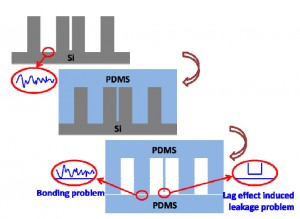
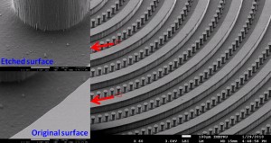
Nowadays, microfabricated silicon has been widely used as a master in PDMS-based soft lithography. It carries the merits of the microelectromechanical system (MEMS) technique, such as being able to construct complex 3D or high aspect ratio micro/nanostructures. However, the silicon master is easy to break during the PDMS moulding process. Due to the lag effects existed in deep reactive ion etching (DRIE) for silicon microfabrication, there will be a high risk of leakage between these two channels after PDMS moulding and bonding, if two parallel microchannels were designed too close, as shown in Fig. 1a. More seriously, the bonding surface of the PDMS replica will follow the morphology of the etched surface (Fig. 1a). Usually the etched silicon surface has high roughness, especially after a deep etching of silicon by DRIE (Fig. 1b), which makes the subsequent PDMS bonding being difficult, sometimes even impossible. To overcome the fragileness of the silicon master, it has been reported that moulding epoxy with PDMS replica, which is prepared by using the original microfabricated silicon as the master, to achieve a durable master in the PDMS moulding process. [1] However, this approach still suffers the aforementioned lag-induced leakage and bonding problems.

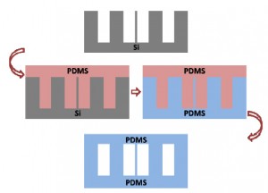
Moulding PDMS with a PDMS master replicated from the microfabricated silicon directly can overcome the aforementioned problems, as illustrated in Fig. 1c. It has been developed by silanizing the PDMS master with tridecafluoro- 1,1,2,2- tetrahydrooctyl- 1- trichlorosilane (in vacuo, 8h[2] or overnight[3]). In this Tip, we optimized the PDMS moulding process with the PDMS replica as the master. The optimal protocol is simple and easy to establish in any labs.

a

b

c

Fig. 1 Moulding PDMS with microfabricated silicon as master. (a) Schematic illustration of the lag effect induced leakage and bonding problems existed in the traditional soft-lithography when the PDMS is replicated from the microfabricated silicon master directly. (b) SEM photo of the microfabricated silicon master used in the present work (with the tilting angle of 45o). Inserted SEM photos give the morphology comparison between the etched silicon surface and the original one. (c) Schematic illustration of the moulding PDMS process with a PDMS master.

What do I need?


Microfabricated silicon, aluminum foil (Select HORECATM, Jinweiyuan Hotel Supplies Co. ltd.), mould release reagent (Micro90®, International Products Corporation, USA), PDMS (Sylgard 184; Dow Corning Co., MI), detergent (commercial available detergent, White CATTM, White Cat co. ltd.), ethanol (MOS grade, Beijing Chemical Reagent Institute).

What else should I know?


Process optimization

The present protocol contains two PDMS moulding processes: The first one is to construct the PDMS master from the microfabricated silicon while the second to make the final PDMS replica directly from the so-prepared PDMS master.

Considering the Corona-triggered PDMS-PDMS bonding technique [4], which will be adopted in the subsequent PDMS-microfluidic device construction, curing at 60oC for an hour of the PDMS pre-polymer prepared following the manufacture guideline was selected as the second PDMS moulding recipe. In this chips and tips, the first PDMS moulding process and the surface treatment of the PDMS master were optimized.

1) Optimization of the first PDMS moulding process

Table 1 Optimization of the first PDMS molding process

The first PDMS moulding process was optimized for the PDMS master preparation as shown in Table 1. Based on the above experiments, we found the optimal recipe for the first PDMS moulding process was curing the PDMS pre-polymer at 120oC for an hour with the mass ratio (Base to Curing agent) of 5:1. (Condition No.4)

2) Optimization of the surface treatment of the PDMS master

Table 2 Optimization of the surface treatment of the PDMS master

Surface treatment is another important factor for the PDMS moulding and was optimized as listed in Table 2. The results indicated that detergent dissolved in 75% ethanol (about 10 w.t.%) was the optimal recipe for the second PDMS moulding process. (Condition No.3) Herein, we name it the modified mold release agent. In later work we also use it for pre-treatment of the microfabricated silicon master.


How do I do it?


1. Make a holder with aluminium foil, according to the shape of the microfabricated silicon master. [5]
2. Mix the PDMS according to the manufacturer’s procedure, but with a mass ratio of the Base to the Curing agent of 5:1.
3. Pre-treat the microfabricated silicon master with the modified mold release agent.
4. Dry the microfabricated silicon master with nitrogen and put it into the holder.
5. Pour the PDMS pre-polymer into the holder, covering the whole microfarbicated silicon master, and then place the holder in an oven at 120oC for an hour.
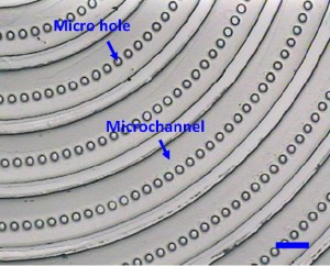
6. Gently peel the PDMS replica (the PDMS master in the second PDMS molding process) off from the microfabricated silicon master. (Fig.2)

Fig. 2 The PDMS master, the PDMS replica from the microfabricated silicon. (The scale bar is 100μm.)

7. Treat the PDMS master with the modified mould release agent. For the deep holes (e.g. some holes with the depth of 100?m in Fig.2), treat the master with the modified mould release agent in the vacuum.
8. Place this PDMS master in a Petri dish, with the moulded-side upwards.
9. Mix PDMS prepolymer again according to the standard manufacturer’s procedure with a mass ratio of the base to the curing agent of 10:1.
10. Pour the PDMS mixture into the Petri dish, covering the whole PDMS master, and then cure at 60oC for an hour.
11. Carefully peel the PDMS replica (Fig.3) off from the PDMS master for the subsequent experiments.

Fig. 3 The final PDMS replica from the PDMS master. (The scale bar is 100μm).

Acknowledgements


This work was financially supported by the 973 Program (Grant No. 2009CB320300).

References


[1] A. Estévez-Torres, A. Yamada and L. Wang,  An inexpensive and durable epoxy mould for PDMS, Chips & Tips (Lab on a Chip), 22 April 2009.
[2] J. R. Anderson, D. T. Chiu, R. J. Jackman, O. Cherniavskaya, J. C. McDonald, H. Wu, S. H. Whitesides and G. M. Whitesides, Fabrication of Topologically Complex Three-dimensional Microfluidic Systems in PDMS by Rapid Prototyping, Anal. Chem., 2000, 72, 3158-3164.
[3] J. L. Tan, J. Tien, D. M. Pirone, D. S. Gray, K. Bhadriraju, and C. S. Chen, Cells lying on a bed of microneedles: An approach to isolate mechanical force, Proc. Natl. Acad. Sci. U. S. A., 2003, 100(4), 1484-1489.
[4] C. Yang, W. Wang, and Z. Li, Optimization of Corona-triggered PDMS-PDMS Bonding Method, in Proceedings of the 4th IEEE International Conference on Nano/Micro Engineered and Molecular Systems, 319-322.
[5] A. O’Neill, J. Soo Hoo and G. Walker, Rapid curing of PDMS for microfluidic applications, Chips & Tips (Lab on a Chip), 23 October 2006.

Digg This
Reddit This
Stumble Now!
Share on Facebook
Bookmark this on Delicious
Share on LinkedIn
Bookmark this on Technorati
Post on Twitter
Google Buzz (aka. Google Reader)

A two-for-one dielectric and hydrophobic layer for digital microfluidics

Mais J. Jebrail, Nelson Lafreniere, Hao Yang and Aaron R. Wheeler
Department of Chemistry, University of Toronto, Ontario, Canada

Why is this useful?


Digital microfluidics (DMF) is a technique in which droplets of reagents in micro- to nano-liter volumes are manipulated by applying a series of electrical potentials to an array of electrodes[1]. In DMF devices, the actuation electrodes are coated with an insulating layer. Upon application of electrical potentials, charges accumulate on either side of the insulator, a phenomenon that can be exploited to make droplets move, merge, mix, split, and dispense from reservoirs. The insulating layer is covered by an additional hydrophobic coating, which reduces droplet sticking to the surface[2]. The instruments and materials required for forming these layers are expensive (tens-to-hundreds of thousands of dollars) and the deposition methods are time-consuming (many hours). We recently [3] demonstrated a new strategy for reusing DMF devices by fitting them with insulating polymer coverings (e.g., food wrap) that are spin-coated with Teflon. Here, we share an even simpler method that is cheap (tens of dollars) and fast (minutes)  featuring a two-for-one insulating and hydrophobic layer formed from laboratory wrap (Parafilm®, Alcan Packaging, Neenah, WI). No Teflon is required for fabricating these devices, and we speculate that this will be useful for laboratories interested in rapid prototyping for various applications.

What do I need?


  • Bottom substrate patterned with working electrodes (typically chromium or gold on glass); electrodes can be formed using conventional cleanroom techniques [4,5] or by rapid prototyping techniques such as microcontact printing [6], laser toner printing [7], or marker masking [8]
  • Indium-tin-oxide coated glass (can be purchased from Delta Technologies Ltd, Stillwater, MN) to serve as top substrate
  • Parafilm® and wax paper backing
  • Scissors
  • Scalpel
  • Hot plate

How do I do it?


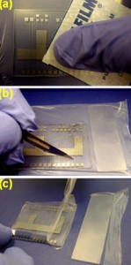
1. With scissors, cut a piece of Parafilm® and stretch the film horizontally and vertically to its limits (a), and place over the bottom plate of the DMF device (with patterned electrodes) (b)

2. With a wax paper apply pressure with your finger on the film to release any air trapped between the electrode(s) and film (a). Then, score film with a scalpel and peel off excess Parafilm® (b,c).

3. Repeat steps 1 and 2 to apply parafilm layer to the top substrate (indium-tin oxide coated glass)
4. Place substrates on hotplate for 30 seconds at 80-85°C.
5. Allow substrates to cool down to room temperature (a), and then assemble the device with a top plate4,5 to dispense, merge and split droplets as shown in Figure (b-e).

What else should I know?


  • A ~4.5 x 4.5 cm piece of Parafilm® stretched to its limits will give a thickness of 6 – 9 mu.gifm.
  • A voltage of 300 – 500V is appropriate for actuation for above thickness.
  • Use of wax paper when applying pressure is important as it avoids contamination of Parafilm® surface.
  • Device can be recycled by simply peeling off old Parafilm® and replacing it with a new film.

References


[1] A. R. Wheeler, Science, 2008, 322, 539.
[2] J. Lee, H. Moon, J. Fowler, T. Schoellhammer, C. J. Kim, Sens. Actuator A-Phys., 2002, 95, 259.
[3] H. Yang, V. N. Luk, M. Abdelgawad, I. Barbulovic-Nad and A. R. Wheeer, Anal. Chem., 2009, 81, 1061.
[4] M. G. Pollack, A. D. Shenderov and R. B. Fair, Lab Chip, 2002, 2, 96.
[5] S. K. Cho, H. J. Moon and C. J. Kim, J. Microelectromech. Syst., 2003, 12, 70.
[6] M. W. L. Watson, M. Abdelgawad, G. Ye, N. Yonson, J. Trottier and A. R. Wheeler, Anal. Chem.,  2006, 78, 7877.
[7] M. Abdelgawad and A. R. Wheeler, Adv. Mater., 2007, 19, 133.
[8] M. Abdelgawad and A. R. Wheeler, Microfluid. Nanofluid., 2008, 4, 349.

Digg This
Reddit This
Stumble Now!
Share on Facebook
Bookmark this on Delicious
Share on LinkedIn
Bookmark this on Technorati
Post on Twitter
Google Buzz (aka. Google Reader)

Quick-connect tubing adapters with small dead volume

Gregory A Cooksey1 and Glynis Mattheisen2

1 Biochemical Science Division, National Institute of Standards and Technology, Gaithersburg, MD
2 Louisiana State University, Baton Rouge, LA

Why is this useful?


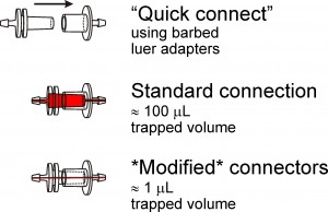
Luer adapters are convenient tools to rapidly and reversibly connect tubing from fluid reservoirs to microfluidic devices. One problem associated with the use of these adapters is that they trap considerable dead volume (approx 100 µl), which dramatically increases the time required to rinse away one fluid when another fluid is to be delivered down the same line. Another common shortcoming of leur adapters is that they are only available for 1.59 mm (1/16″) and larger inner diameter (ID) tubing. We demonstrate how to modify luer adapters to fit almost any size tubing while dramatically reducing the dead fluid volume trapped inside the connector.

What do I need?


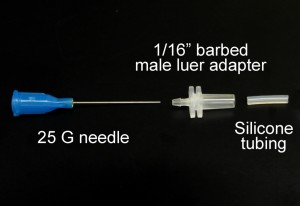
  • 25 mm or longer needle or stainless steel tubing.  We use blunt 25 gauge needles (McMasterCarr # 75165A761). Use extreme care with exposed needles!
  • Polypropylene 1/16 in. barbed male luer adapter (Cole Parmer #R-45503-07)

  • Silicone tubing with large enough ID to slip over needle but small enough outer diameter (OD) to fit inside luer adapter.  We use 0.8 mm ID silicone tubing (Cole Parmer #R-06411-60)
  • Poly(dimethylsiloxane) (PDMS) (Sylgard 184, Dow Corning)
  • Tubing to attach to the connectors.  We use 0.51 mm ID tygon microbore tubing for 25 gauge needles (Cole Parmer #R-06418-02)
  • Dremel 300 (Dremel) or similar tool with cutoff wheel (Dremel #409)

How do I do it?


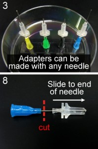
1. Insert the needle into the barbed end of the 1/16 in. barbed male luer adapter.
2. Thread about 15 mm of silicone tubing onto the needle and push the tubing to the base of the adapter using tweezers.  This keeps the needle centered in the adapter, and the silicone tubing bonds well to the PDMS.  The tubing should stick out of the adapter about 3mm, which accounts for extra dead space that exists in needle hubs and other female luer adapters.
3. Place the hubs of the needles you’ve made onto a dish standing upright.  Double-sided tape on the bottom of the dish will help keep the needles upright.
4. Fill the inside of the luer adapters with PDMS.  We find it helpful to use a syringe (with an 18 G needle) to inject PDMS into the adapters.  At this point it is recommended to de-gas the PDMS by placing it in a vacuum jar for several minutes.
5. Place the dish in an oven at 70ºC to cure for at least 2 hours.  Check after about an hour to make sure the luer hubs stayed filled with PDMS.  You may have to add some additional PDMS if some has leaked out the barbed end.
6. Remove the needle from the dish and clear away excess PDMS from the base of the needle and the outside of the adapter.
7. Push the adapter to the tip of the needle.
8. Cut away the needle luer hub.  A wire cutter can be used, but we prefer using a Dremel tool fitted with a cutting wheel.  It is less likely to compress the tubing closed.  Polishing the end of the needle with the cutting wheel is also recommended.
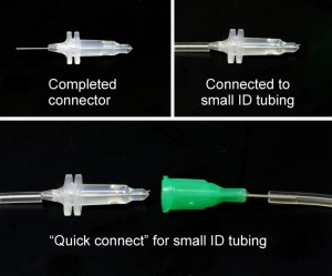
9. Insert the needle extending from the barbed end of the adapter into 0.51 mm ID Tygon tubing.

What else should I know?


“Quick connects” for the same or different ID tubing can be made by plugging the connector into the luer hub of a blunt needle that fits tightly inside the desired tubing.

We have also tried filling the luer hubs with PDMS and curing them prior to inserting needles or stainless steel tubing.  Because the needles are flexible, we find it difficult to keep the needles straight through the center of PDMS core.  This method also typically plugs the needle, so a new needle would be necessary to replace the coring needle.

Disclaimer: Certain commercial equipment, instruments or materials are identified in this report to specify adequately the experimental procedure. Such identification does not imply recommendation or endorsement by the National Institute of Standards and Technology, nor does it imply that the materials or equipment identified are necessarily the best available for the purpose.

Digg This
Reddit This
Stumble Now!
Share on Facebook
Bookmark this on Delicious
Share on LinkedIn
Bookmark this on Technorati
Post on Twitter
Google Buzz (aka. Google Reader)