Archive for the ‘Interfacing and integration’ Category

Interfacing of microfluidic devices

Tamal Das
Department of Biotechnology, IIT Kharagpur-721302, India

Debapriya Chakraborty, Suman Chakraborty*
Department of Mechanical Engineering, IIT Kharagpur-721302, India
* e-mail: suman[at]mech.iitkgp.ernet.in

Why is this useful?


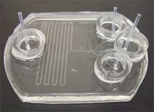
The integration of PDMS chips, with pumps or connections to reservoirs, has been found to pose serious difficulties because of its associated problems in leaking, interfacing with tubing, etc. Here, we present a simple approach for making reservoirs and also connecting devices with tubing for interfacing with pumps, without the aid of commercially available connectors and using commonly available consumables in the laboratory.

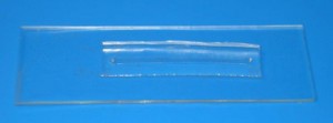
The PDMS mould is bonded with glass in two ways – using hydrophilic and hydrophobic means. Hydrophilic bonding involves using a plasma cleaner for oxidation. Hydrophobic bonding is done using a PDMS mixture. Here, we report easy and cost effective hydrophilic and hydrophobic bonding protocols. For example, the hydrophilic bonding can also be done without the use of conventional plasma oxidation.

What do I need?


  • PDMS base and curing agent (SYLGARD 184 silicone elastomer kit) in 10:1 wt/wt ratio
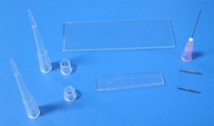
  • micropipette tip (2-200 µl pipette tips)
  • 20 gauge (outer diameter) needles
  • tubing (20 gauge inner diameter)
  • Piranha solution (H2O2 and H2SO4 solution in 1:1 vol/vol ratio)

Figure 1

What do I do?


1. Cut the syringe needles to the desired length (approximately 1.5 cm), preferably using wire electrical discharge machining. Any other needle cutter can be used if it can cut sharply the ends of the needles.

2. Punch holes in the PDMS mould using these needles at the inlet/outlet.

3. Bonding the PDMS mould to the substrate (Figure 2):

  • Hydrophilic bond:
  1. Oxidize the glass slide and the PDMS mould in freshly prepared Piranha solution.
  2. Dip the glass slide in the solution for 5 mins, and the PDMS mould for 10 secs. Dipping the PDMS mould for larger times may lead to damage to the mould because of strong oxidation
  3. Rinse them in deionised water at least three times. This step is required to remove any residual acid as well as to prevent hydrophobic recovery.
  4. Dry both the glass slide and the mould using a compressed stream of dry nitrogen gas.
  5. Place the mould over the glass slide and heat it at 70°C for 30 minutes.
  • Hydrophobic bond:
  1. Coat the glass slide with a thin layer (~ 10 µm thickness) of PDMS mixture (preferably by spin coater).
  2. Heat it at 70°C for 7 mins (this makes the PDMS hardened but still sticky)
  3. Place the PDMS mould on the sticky PDMS surface. In order to avoid wrinkles and air gaps, lay the mould down from one end to the other.
  4. Heat it for at least 30 mins at 70°C.

Figure 2

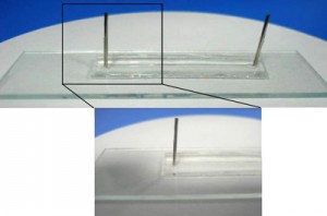
4. After bonding the PDMS mould to the glass, place the needles in the holes. Apply a small amount of PDMS mixture to the cylindrical surface of the needles. The PDMS mixture slowly settles down near the junction. Applying larger quantities of PDMS mixture may lead to seepage into the channel through the junction. Heat it immediately for 10-15 mins at 70°C. (Figure 3)

Figure 3

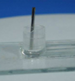
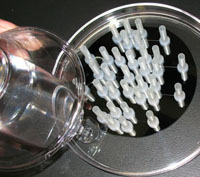
5. Cut a small piece of micropipette tip with at least one planar surface. Put a bit of PDMS mixture around the periphery of the planar surface. Place it centering the needles and heat it for 20 mins at 70°C. This makes the reservoirs. (Figure 4)

Figure 4

6. Pour PDMS mixture into the reservoirs around the syringe needle tips and heat it at 70°C for 25-30 mins until the supports become rigid. This provides the support for the needles. (Figure 5)

Figure 5

The tubing can be connected to these cut out needles, and the other ends connected to a syringe or peristaltic pump (Figure 6). If the connection to the pump is not desired and only the reservoirs are required then steps (1, 4, 6) are not required.

Figure 6

Digg This
Reddit This
Stumble Now!
Share on Facebook
Bookmark this on Delicious
Share on LinkedIn
Bookmark this on Technorati
Post on Twitter
Google Buzz (aka. Google Reader)

Overcoming interfacing issues by adding fumed silica

Alexander Iles
Dept. Chemistry, University of Hull, Cottingham Rd, Hull, HU6 7RX, UK

Problem


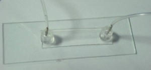
In microfluidics it is often necessary to interface chips using capillaries or plastic tubing. This can introduce a number of problems. For example, with glass chips it is rarely the case that the tubing or capillary is a perfect match for the reservoir hole that has been drilled into the device. Hence when using adhesives to attach tubing, the glue can seep down into the microdevice and clog its channels. Alternatively, with PDMS it is difficult to find anything that will stick to it and also securely hold a connecting tube in place. Nanoports can be used to interface devices, but they are expensive [1]. Small pieces of PDMS can be plasma bonded to a chip to create ports [2], but this involves extra fabrication steps and a plasma oven.
The solution:

To use fumed silica to create thixotropic adhesives. Adding fumed silica to epoxy resins or to PDMS creates adhesives that are extremely viscous and will not flow. Hence it can be added to epoxy resins to prevent seepage between access holes and tubing with glass chips and also it can be added to PDMS to make highly effective ports for PDMS chips.

Materials


  • A small quantity of premixed epoxy resin or PDMS
  • Fumed silica. Fumed silica is manufactured by Degussa and can be obtained as a free sample by visiting their website[3]
  • A container and a spatula for mixing

Procedure


1. Take a small quantity of your resin of choice (epoxy or PDMS). Place this in your mixing container.

2. To the resin, add a small amount of fumed silica, and using a spatula, mix it into the resin. A good starting point is 1 part fumed silica to 11 parts pre-mixed PDMS (by weight). Warning! Always wear a dust mask when handling fumed silica, it is like very fine dust. One sneeze and it will go everywhere! Bear in mind the working life of your epoxy resin, some resins set in 5 minutes or less, which will not give much time for mixing in fumed silica.

3. Once the fumed silica has been incorporated into the resin, add more as necessary to obtain the required thixotropy. Then it is ready for application.

4. For glass chips, always wipe down the surface of the device with acetone and allow it to evaporate before applying epoxy, to ensure a good bond.

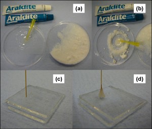
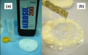
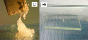
5. Place the tube or capillary into the hole. Use a pipette tip or small applicator to apply a small blob of adhesive around the interface. The resin mixture will not flow, so it will be necessary to smooth it around the tube or capillary with the applicator. The procedure is similar for PDMS devices, except that a hole must first be bored into the chip, the tube inserted and then the thixotropic PDMS applied. In both cases, cure times can be reduced and adhesion strengths improved if an oven at 60-70 ºC is used for curing. Refer to Figures 1 and 2 for step by step photographic explanations and further details.

Figure 1. Procedure for making thixotropic epoxy for interfacing glass chips: (a) Mix the epoxy in a suitable container and have some fumed silica ready for use. (b) Add the fumed silica and mix in. (c) Insert a capillary or tube into a hole on the glass chip, after wiping it with acetone. (d) Apply thixotropic epoxy to the interface between the chip and the connector and leave to cure.

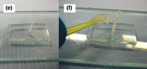
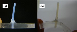
Figure 2. Procedure for making thixotropic PDMS for interfacing PDMS chips: (a) Mix the PDMS in a suitable container and have some fumed silica ready for use. (b) Add the fumed silica and mix in. (c) The PDMS should now look like this. (d) Cut a hole using a boring tool in your PDMS chip. (e) Insert a tube (e.g. PTFE) of a suitable size into the hole on the PDMS chip. (f) Apply thixotropic PDMS to the interface between the chip and the connector tube. (g) Leave it to cure, either at room temperature or at 60-70 ºC. (h) The completed interface. A silica capillary from, for example, a syringe pump, can now be securely inserted into the PTFE tubing and removed again as often as required without leaking. The PTFE tubing has an I.D. of 300 µm, which makes a good interference fit with standard 375 µm O.D. silica capillaries.

Conclusion


Adding fumed silica to PDMS or epoxy resins allows the researcher to fine tune the viscosity of their system as desired. Thixotropic PDMS is probably one of the best materials for interfacing PDMS devices, since few things will stick better to PDMS than PDMS itself!
References


[1] C. Koch, J. Ingle, and V. Remcho,  Bonding Upchurch® NanoPorts to PDMS, Chips & Tips (Lab on a Chip), 12 February 2008.

[2]  S. Mohanty, D. J. Beebe and G. Mensing, PDMS connectors for macro to microfluidic interfacing, Chips & Tips (Lab on a Chip), 23 October 2006.

[3] http://www.aerosil.com/aerosil/en/default

Digg This
Reddit This
Stumble Now!
Share on Facebook
Bookmark this on Delicious
Share on LinkedIn
Bookmark this on Technorati
Post on Twitter
Google Buzz (aka. Google Reader)

Reusable, robust NanoPort connections to PDMS chips

Jesse Greener, Wei Li, Dan Voicu and Eugenia Kumacheva
Department of Chemistry, University of Toronto, 80 St. George Street, Toronto, Ontario, Canada

Why is this useful?


Typical fluidic connections to PDMS chips consist of tubing inserted into a punched inlet, held in place by glue, for example, a cured epoxy glue. These connections can fail at low pressures because of weak adhesion of the glue to PDMS. In addition, insertion of the tubing directly into the inlet may affect the flow if the tubing is pushed right to the bottom of the channel, thereby increasing hydrodynamic resistance. This is particularly a problem for microchips made from a thin layer of PDMS. Furthermore, even subtle changes to hydrodynamic resistance at the inlet can affect flow rates from pressure-driven sources or cause differential flow rates through inlets which are supplied from a manifold that is being driven from a single source.

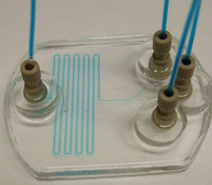
Upchurch has devised a low fluidic resistance chip connection system made from the polymer PEEK called a NanoPort, which can easily accommodate new feeds via a threaded nut and ferrule system.[1] However, this device is designed as a single-use port which is sealed to the chip via a permanent bond at its base using an adhesive ring. The adhesive ring does not stick well to untreated PDMS but plasma treatment of the fully cured PDMS surface has been reported to enhance the bond between the NanoPort/adhesive ring assembly and PDMS.[2] This technique has the advantage of being able to handle working pressures of between 30-50 PSI, but suffers from the single use nature of the adhesive ring. For connections to PDMS chips, Upchurch recommends that the NanoPort be imbedded in the PDMS during microchip curing. This technique is not ideal because the sealing surface area is relegated to the bottom of the NanoPort only, and the semi-cured state of the PDMS is not conducive to creating a strong bond. Other groups have fabricated their own, low cost PDMS connectors, which may be a convenient substitute for the NanoPort in low pressure applications.[3]

This tip reviews an alternative approach; encasing the NanoPort in PDMS at the surface of a previously cured PDMS microchip. Benefits include NanoPort reusability (after liberating them from the PDMS encasing) and higher useable pressure ranges (we determined that up to 85 PSI can be achieved). This technique can be easily adapted to chips of any materials which make a strong bond with PDMS, including glass and polycarbonate.

What do I need?


  • PDMS SYLGARD 184 silicone elastomer base & curing agent (Dow Corning)
  • Upchurch NanoPort assembly
  • Plasma cleaning system for PDMS surface oxidation
  • A heat source (convection oven)
  • One 3 cm-long piece of tubing with 1.59 mm OD (1/16 inch) per inlet
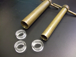
  • Knife or 2 differently sized cork borers, the smallest of which should be at least 1.0 cm (we used 1.7 and 1.0 cm diameter)

What do I do?


1. Prepare the PDMS chip, ensuring that access holes with diameter of roughly 1.5 mm are punched into the surface.

2. Punch or create PDMS rings with thickness no less than approximately 5 mm.

Figure 1

3. Insert 1/16 inch OD tubing into the inlet holes to block PDMS from entering the device.

Figure 2

4. Plasma bond the PDMS rings centered around the inlet holes on the PDMS chip (we use 90 seconds at 600 mTorr). This serves as a reservoir for liquid PDMS for the following steps.

Figure 3

5. Coat the bottom of the reservoir with less than 1 mm of liquid PDMS, then place the NanoPort base over the tubing in the PDMS reservoir. Make sure at this stage that no air bubbles are trapped at the bottom of the NanoPort in the groove designed for the o-ring, which we are not using for this application. This can be accomplished by rotating the port’s base in the liquid PDMS within the reservoir while sliding it up and down slightly around the tubing to allow air to escape. Degassing under vacuum may also work.

6. Finish filling the reservoir with PDMS, being careful not to get any in the threaded area of the NanoPort or inside the tubing, and heat cure (we used 4 hours at 74ºC).

7. After curing, pull the tubing out of the inlet. If any PDMS leaked into the threaded part of the NanoPort base this can be removed with tweezers or by repeatedly connecting and disconnecting the base’s male threaded counterpart (nut). Clear debris with compressed air.

8. Connect the nut and ferrule (or coned nut) to 1/16 OD tubing, attach to the NanoPort base and supply liquid or gas to the chip.

Figure 4

What else should I know?


In this example, we apply this technique to mounting NanoPorts on to a PDMS microchip. In theory, other substrates can benefit from this technique as long as they can be bound to PDMS either by plasma treatment, or by curing liquid PDMS to it. Also, the PDMS ring provides a leak-proof reservoir for liquid PDMS which results in a clean finish when affixed to the surface via plasma treatment. However, rings can also be stuck to the surface via curing a thin coat of liquid PDMS between the two, though the finish may not look as nice.

Our pressure tests probed the strength of the bond between the NanoPort and PDMS. Therefore a flat piece of PDMS substrate was used instead of a microchip with channel structures. By progressively increasing the pressure of an inert gas (N2) being supplied to the NanoPort assembly it was determined that in every case the failure occurred between its base and the top of PDMS substrate. In our tests, failure occurred between 40 and 85 PSI. In theory, the assembly would benefit from more contact area between the PDMS/NanoPort assembly and the PDMS chip. A wider PDMS reservoir would accomplish this, though inlet spacing would have to be adjusted to account for the larger assembly footprint over each inlet. In addition, changing the ratio of silicone elastomer to curing agent and/or implementing this technique on a surface that has not yet fully cured or has been freshly plasma treated may also help to strengthen this bond. The same NanoPorts used in previous tests were then attached to a working microfluidic chip and subjected to increasing gas pressure. In this case, the chip itself separated before the reusable NanoPort connection failed.

References


[1] http://www.upchurch.com/PDF/I-Cards/N4.PDF
[2] C. Koch, J. Ingle, and V. Remcho,  Bonding Upchurch® NanoPorts to PDMS, Chips & Tips (Lab on a Chip), 12 February 2008.
[3] S. Mohanty, D. J. Beebe and G. Mensing, PDMS connectors for macro to microfluidic interfacing, Chips & Tips (Lab on a Chip), 23 October 2006.

Digg This
Reddit This
Stumble Now!
Share on Facebook
Bookmark this on Delicious
Share on LinkedIn
Bookmark this on Technorati
Post on Twitter
Google Buzz (aka. Google Reader)

Bonding & sealing of components in PDMS by deposition of micro-drops of PDMS using micropipette

Arash Noori and P. Ravi Selvaganapathy
Department of Mechanical Engineering, McMaster University, Hamilton, Ontario, Canada

Why is this useful?


Sealing and bonding of components in PDMS (poly-dimethylsiloxane) molds using PDMS as glue is as challenging as it is effective because of the ability of PDMS glue to conform to nanometer sized features.  An ever present problem is the flow of the uncured PDMS into undesired locations because of the deposition of large drops and the low viscosity of PDMS.  This can lead to clogging of interconnects, channels and on-chip components in the assembly process thus damaging the device or necessitating repair.

This tip presents a method for the deposition of microdrops of uncured PDMS using a micropipette and probe station micromanipulator to allow for highly controlled and localized sealing and bonding.  This process can be used to seal interconnects in critical regions, to repair cracks and to bond components into microfluidic devices.  It can be used for any process that requires highly localized deposition of PDMS to act as glue or sealant.  For demonstration purposes this article will describe the process to embed and seal a 360 µm OD/20 µm ID fused silica capillary into a PDMS microfluidic device without clogging the opening.

What do I need?


  • Fully cured PDMS microfluidic device
  • Sylgard 184 silicone elastomer kit (Dow Corning)
  • Probe station with microscope and micromanipulator probe
  • Micropipette puller and borosilicate glass tubes (1 mm OD/0.5 mm ID, Sutter Instrument Company, California, USA) to fabricate micropipettes (may also be purchased from WPI Inc, Florida, USA)
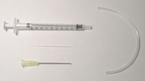
  • Syringe (1 ml), needle (20G1½) and tubing (Tygon 2.4 mm OD/0.7 mm ID) (Figure 1)
  • Epoxy
  • Source of heat (hotplate or oven)

Figure 1

What do I do?


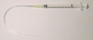
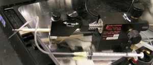
1. Connect the un-pulled end of the micropipette and the needle to opposite ends of Tygon tubing and seal using epoxy. (Figure 2)  The tubing should be long enough to allow for pumping of the PDMS without disturbing the micropipette tip.

Figure 2

2. Carefully attach the micropipette to the probe station micromanipulator tip using adhesive tape.  Make sure that it is firmly attached to the probe. (Figure 3)

Figure 3

3. Place the PDMS device onto the probe station and locate the place where deposition of the microdrops of PDMS is desired.  Refocus and move the micropipette tip to the centre of the viewing area of the microscope.

4. Withdraw a small amount (<1 ml) of 1:30 ratio PDMS into the syringe and connect to needle.

5. Very slowly begin injecting PDMS into the tubing and micropipette, monitoring the movement of the PDMS in the micropipette until a drop of PDMS is visible at the micropipette tip.

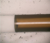
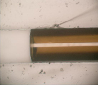
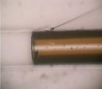
6. Refocus the microscope to the PDMS substrate below and bring the deposition area in alignment with the micropipette tip.  Slowly start moving the probe station micromanipulator tip down until both the PDMS substrate and the micropipette are visible.  Readjust the micropipette tip to the desired location using the micro adjusters.  Slowly move the micropipette tip down.  Once the micropipette tip makes contact with the PDMS substrate pause and let the PDMS drop flow into the desired region.  More PDMS can be deposited by gently applying pressure to the syringe to cause more flow of PDMS to the deposition area. (Figure 4)

7. After deposition is complete, place the covered PDMS substrate onto a hotplate at ~95 ºC and cure for 10 minutes.

Figure 4a

Figure 4c

Figure 4b

Figure 4d

References


http://www.tygon.com/
http://www.dowcorning.com/
http://www.sutter.com/
http://www.wpiinc.com/

Digg This
Reddit This
Stumble Now!
Share on Facebook
Bookmark this on Delicious
Share on LinkedIn
Bookmark this on Technorati
Post on Twitter
Google Buzz (aka. Google Reader)

Lamination of plastic microfluidic devices

Daniel Olivero and Z. Hugh Fan
Department of Mechanical and Aerospace Engineering, University of Florida, Gainesville FL, USA

Why is this useful?


Bonding is a critical step in fabricating plastic microfluidic devices.[1] It is a process to seal microfeatures (e.g. channels) in a plastic substrate with a cover film. Lamination is one of the best methods to achieve a successful bond, with no air bubbles between the plastic substrate and film, no distortion of microfeatures, and minimum deformation of the device.[2] The parameters affecting the quality of lamination include the heating temperature, the pressure placed on the assembly, and the lamination process.[2] This tip describes using a commercially available, tabletop, roller laminator to seal a plastic substrate with a cover film. The plastic substrate (1.5 mm thick) is made from a cyclic olefin copolymer (COC) resins (Zeonor® 1020) and the film is a 100 µm thick COC film (Topas® 8007).

What do I need?


  • A plastic substrate with microchannels (1″ x 3″)
  • A thin film (1″ x 3″)
  • Metalized Mylar films
  • A hot plate
  • A conventional laminator (GBC® Catena 35, Lincolnshire, IL)

The set up


Figure 1.

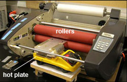
To preheat the plastic substrate to a temperature close to the lamination temperature, the laminator is modified as follows. The feed table in front of the rollers is removed and replaced with a hot plate as shown in Figure 1. The hot plate is raised to align the plate surface with the gap between the two rollers. The hot plate is used to preheat the plastic substrate so that it is easier to reach the required temperature for lamination of COC devices.

What do I do?


1. Clean both the plastic substrate and the cover film in purified water in an ultrasonic bath. Then rinse them in acetone and dry them in a clean air in a laminar hood. Make sure that both the substrate and the film are completely dry before proceeding.

2. Assemble the plastic substrate with the cover film. In our case, alignment is not required since all features are in the substrate. If any feature is made in the cover film, accurate alignment is likely needed.
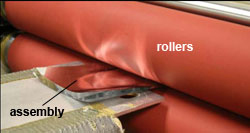
Figure 2.

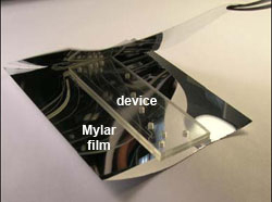
3. Cut two pieces of Mylar sheets sufficiently large to cover both the plastic substrate and the cover film. Place them between two Mylar sheets as shown in Figure 2. The Mylar sheets are used to prevent the texture of the rollers from being transferred to the plastic device, maintaining a smooth surface of both substrate and film.

Figure 3.

4. Place the assembly of the plastic substrate, the cover film and the Mylar sheets on the hot plate. Make sure that the cover film is at the bottom side, so that the heat is easier to be transferred to the interface between the film and substrate. Place a microscope slide and weights (2 x 44 g) on top of the assembly to ensure the assembly is in contact with the hot plate, as shown in Figure 3. The slide allows a uniform pressure placed on the assembly. For the specific plastic substrate and film, the hot plate is set at a temperature of 73ºC. Other plastic materials likely require different temperatures as discussed in the literature.[2,3]  Allow the assembly to be heated for four minutes.

Figure 4.

5. After the completion of the pre-heating, remove the weights and the slide from the assembly. The laminator rollers should have been heated to a temperature of 124ºC. The gap between the rollers is set at 3 mm and the roller speed is set at 3 feet/minute. Press the “run” button of the laminator and gently slide the assembly into the rollers. Make sure that the plastic substrate and the film do not become misaligned while sliding. Once the assembly enters the rollers it should move by itself through the laminator as shown in Figure 4. If needed, the device may be rolled through the laminator once more to ensure a complete lamination.

6. Once completed a functional microfluidic device is obtained, as shown in Figure 5. This device was used for two-dimensional protein separation by integrating isoelectric focusing (IEF) and polyacrylamide gel electrophoresis (PAGE).[4] The device was filled with a dye for easy visualization of channels. Note that this lamination method can be used for other types of materials but the variables such as the lamination temperature likely need to be adjusted for a perfect lamination.

Figure 5. Cyclic olefin copolymer device

Acknowledgements


This work is supported in part by the grants (48461-LS and 52924-LS-II) from the USA Army Research Office and the startup fund from the University of Florida.

References


[1] L. J. Kricka, P. Fortina, N. J. Panaro, P. Wilding, G. Alonso-Amigo and H. Becker, Lab Chip, 2002, 2, 1-4.
[2] C. K. Fredrickson, Z. Xia, C. Das, R. Ferguson, F. T. Tavares and Z. H. Fan, J. Microelectromech. Syst., 2006, 15, 1060-1068.
[3] M. L. Hupert, W. J. Guy, S. D. Llopis, H. Shadpour, S. Rani, D. E. Nikitopoulos, S. A. Soper, Microfluid. Nanofluid., 2007, 3, 1-11.
[4] C. Das, J. Zhang, N. D. Denslow, and Z. H. Fan, ZH. Lab Chip, 2007,  7, 1806-1812.

Digg This
Reddit This
Stumble Now!
Share on Facebook
Bookmark this on Delicious
Share on LinkedIn
Bookmark this on Technorati
Post on Twitter
Google Buzz (aka. Google Reader)

Integrated reservoirs for PDMS microfluidic chips

T. Liu, E. V. Moiseeva, and C. K. Harnett
Electrical and Computer Engineering, University of Louisville, Louisville, KY 40208, USA

Purpose


Reservoirs are sometimes preferable to tubing connections, especially for pressurized or gravity-driven flow, for installing electrode wires into open ports, or for storing a PDMS chip pre-loaded with water to preserve its hydrophilicity after plasma treatment. However, gluing individual reservoirs onto a finished chip can be messy and prone to clogging ports and channels with silicone, and the assembly may be fragile. These reservoirs, made from inexpensive nylon spacers, are embedded in the chip by PDMS casting, eliminating several of these problems. They can run with up to 30 psi gas pressure-driven flow when provided with connections for pressurized tubing.

Materials


Consumables:

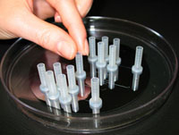
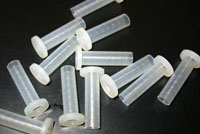
  • Flanged nylon shoulder spacers (McMaster Carr part 91145A154, shown in Figure 1)
  • PDMS compound (Dow Corning Sylgard 182 or 184)

Figure 1: Flanged nylon shoulder spacers for use as reservoirs

For optional gas pressure-driven flow:

  • Epoxy (Scotch-Weld DP-420)
  • Hose barb connectors (McMasterCarr part 51525K211)

Tools:

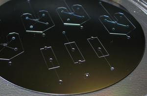
  • A mold for casting chips (Figure 2)
  • PDMS weighing and degassing equipment
  • A punching tool for creating ports in PDMS, such as thin-walled stainless hypodermic Tubing (Small Parts Inc., part HTX-22X or similar)
  • Tweezers
  • X-Acto knife

Figure 2: A microfabricated mold on a 4-inch silicon wafer

Procedure


1. Make a mold for your design, with reservoir locations 1 cm apart or more. This method was tested on SU-8 molds on silicon wafers, with resist thickness from 60 to 170 microns, without any special mold release treatment.

Pour a thin (~1 mm) layer of PDMS over the mold, and cure until solid. Place the nylon standoffs on top of the PDMS layer, over the ends of your channels, flange side down. Later you will punch to connect the reservoir with the channel on the underside of the chip. These reservoirs easily stay upright if the PDMS is still a bit sticky. (Figure 3)

Figure 3: Reservoirs are placed on a thin layer of PDMS cured over the mold

Figure 4: A second layer of PDMS holds the reservoirs in place

2. Pour a second 2 mm or thicker layer of PDMS around the reservoirs, covering the flanges to anchor them. (Figure 4) It doesn’t matter if PDMS seeps into some of the reservoirs. Let the PDMS level out, then cure until solid. The nylon reservoirs are OK at temperatures up to 80ºC.

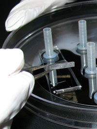
3. Cut out individual devices with the X-Acto knife and peel off devices plus embedded reservoirs. It’s best to grip the devices at the PDMS using tweezers, rather than pulling on the reservoirs. (Figure 5)

Figure 5: Reservoirs and channels are removed from the mold together

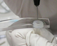
4. Use the punching tool to create a port in each reservoir that connects to the microfluidic channel, making sure to remove a core of PDMS from each port. This can be done from the channel side (Figure 6) or from the reservoir side.

Figure 6: Punched ports connect reservoirs to channels

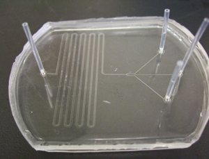
5. Bond the punched chips to a glass, PDMS or other substrate using plasma activation or other method of choice. Figure 7 is a side view of a bonded chip, showing anchored reservoirs and punched ports on a molded PDMS chip, attached to a blank PDMS slab on a glass slide.

Figure 7: Side view of a sealed chip showing sunken reservoirs and ports

6. (Optional, for gas pressure-driven flow) Use epoxy to attach hose-barb connectors to the tops of any reservoirs you want to pressurize. Gas can be provided to each reservoir using Tygon tubing. The 1/16″ hose barb to Luer connectors, and 1/16″ ID Tygon tubing are a good match to the size of these reservoirs. Gluing adjacent Luer connectors together can help strengthen the assembly when several gas connections are anticipated.

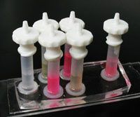
7. Fill reservoirs through the open tops or through the bonded-on hose barbs. Dispensing from a syringe with a long needle or a needle threaded into a small diameter piece of tubing helps prevent trapped air by filling from the bottom up. Figure 8 shows a filled chip with barbs for gas tubes.

8. While these reservoirs have been pressurized up to 30 psi before delaminating, they are easily removed from the chip by bending them sideways. Reservoirs can be peeled out of old chips for re-use if needed.

Figure 8: A filled chip ready for gas pressure-driven flow
Digg This
Reddit This
Stumble Now!
Share on Facebook
Bookmark this on Delicious
Share on LinkedIn
Bookmark this on Technorati
Post on Twitter
Google Buzz (aka. Google Reader)

Quick and cheap syringe-tubing interfacing

Rodrigo Martinez-Duarte and Marc Madou
BioMEMS Research Laboratory, Department of Mechanical & Aerospace Engineering, University of California, Irvine. Irvine, CA.

Why is this useful?


This tip describes an easy, quick and cheap way to interface syringes to 1/16″ OD (outer diameter) tubing for low and medium pressure applications.  This methodology allows for very quick fabrication with off-the-shelf components as well as modularity since connectors can be easily swapped to other syringes, in contrast to some connecting methods which require connector fabrication for each syringe used.  The connector is very easy to use.

We use 1/16″ OD tubing since many compatible parts such as Y connectors, valves and others are available through online vendors (e.g., Upchurch).

What do I need?


  • 1/16″ OD tubing. A wide variety of tubing materials and sizes are available from Upchurch.  In particular we have used Teflon tubing (catalog number 1620). You could also find the connector at Upchurch (TEFZEL, catalog number P-870)
  • Female Luer to 1/16″ ID (inside diameter) Barbed connector, shown in Fig. 1. A wide choice of materials for connectors are available from Gosina.
  • 3M  Polyolefin Heat Shrink (HS) Tubing 3/64″. Although we have used 3M tubing (Polyolefin Heat Shrink Tubing 3/64″) heat shrink tubing with ID of 1/16″ should work as well. HS tubing is available from a number of suppliers including Fisher.
  • Heating element. A soldering iron would be the most common heating element. You can get a basic one from Fisher (catalog number S50350).

Figure 1. Barbed to female luer connector

What do I do?


1. Wear gloves before starting. You don’t want to introduce impurities during fabrication that could contaminate your device channel in future experiments.
2. Cut around 1 cm of HS tubing.
3. Cut desired length of 1/16″ OD tubing. (If you don’t have a special cutter, use scissors instead of knife to assure a cleaner cut.)
4. Sterilize all components with isopropanol for 2-3 minutes then blow dry.
5. Take the HS tubing. Insert one end to the barbed side of the connector. Make sure tubing is  inserted all the way to the base of the connector (~5 mm).
6. On the other end insert the 1/16″ OD tubing. Insert for around 2-3 mm.
7. Leave around 2 mm of HS tubing length between the barbed connector and the 1/16″ OD tubing; it will allow you to have up to 90 degree angles between your tubing and the syringe since once HS tubing is heat shrunk it will be very flexible.
8. Using the heating element, apply heat along all the HS tubing. Connections will further seal as tubing shrinks. Do not apply too much heat or you might melt the 1/16″ OD tubing or the connector.
9. The finished connector is shown in Figure 2.

Figure 2. Completed connector

What else should I know?


These connectors have been tested with DI water, alcohol, yeast samples, diluted YPD growth medium, air and sodium dodecyl sulfate with reliable performance.

The connector can be dismantled by just pulling components apart. The barbed connectors and 1/16″ OD tubing are not damaged and can be reused.

Digg This
Reddit This
Stumble Now!
Share on Facebook
Bookmark this on Delicious
Share on LinkedIn
Bookmark this on Technorati
Post on Twitter
Google Buzz (aka. Google Reader)

A simple interface between a PDMS microfluidic device and a syringe

Jeonggi Seo and Meng H. Lean
Palo Alto Research Center, Palo Alto, CA, USA

Why is this useful?


Syringes are commonly used to supply or collect liquid samples for microfluidics. However, interfacing between a microfluidic chip and syringe is problematic due to their size difference. Plastic tube connectors or Luer stubs have been used as interfacing methods, but they increase sample dead volume and thus experimental cost. The goal of this tip is to provide an inexpensive and simple interface, with minimized sample dead volume, between a microfluidic device and syringe.

Figure 1.

What do I need?


  • 18 gauge blunt needle
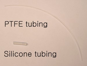
  • PTFE microbore tubing (0.012″ID x 0.030″OD, Cole Parmer)
  • Silicone (platinum-cured) tubing (1/50″ID x 1/12″OD, Cole Parmer)
  • B-D Disposable Syringes 1 mL

What do I do?


1.Punch access holes into your PDMS device with an 18 gauge blunt needle.

2.Cut a segment of silicone tubing ~10 mm long. (Figure 1)

3.Cut a segment of PTFE microbore tubing with desirable length for your set-up.

Figure 2.

4.Insert the piece of silicone tubing inside the 1 ml syringe tip. Make sure the silicone tubing reaches the inner chamber of the syringe but doesn’t disturb piston movement. (Figure 2a-c)

5.Insert the PTFE tubing into the inserted silicone tubing. (Figure 2d)


Figure 3.

6. Load your sample into the syringe

7. Insert the free end of the PTFE tubing into the access hole on your PDMS device (Figure 3). Since no adhesive is involved, the PTFE tubing can be disposed of or reused after cleaning.

References


S. Mohanty, G. Mensing and D. J. Beebe, PDMS connectors for macro to microfluidic interfacing, Chips & Tips (Lab on a Chip), 23 October 2006.

Digg This
Reddit This
Stumble Now!
Share on Facebook
Bookmark this on Delicious
Share on LinkedIn
Bookmark this on Technorati
Post on Twitter
Google Buzz (aka. Google Reader)

PDMS connectors for macro to microfluidic interfacing

Swomitra Mohanty, David J. Beebe
University of Wisconsin Department Biomedical Engineering
Glennys Mensing
University of Illinois Department of Mechanical & Industrial Engineering

Why is this useful?


The purpose of this Tip is to show a simple method to connect the microfluidic world to the macro world.  Microfluidic devices are constructed from a variety of materials including glass, silicon, and polymers.

No matter how microfluidic devices are constructed, one common problem has been employing a user friendly method to connect standard fluidic equipment such as syringes, to the microfluidic device.  Often researchers attempt to use commercially available micro-tube fittings by gluing them to ports on a microfluidic device.  These fittings are small in size and difficult to work with and the glue can clog the port.  To solve this problem we employ an in house fabricated PDMS connector that consists of a hole through the center and uses double-sided adhesive to connect to the microfluidic device.

What do I need?


  • PDMS SYLGARD 184 silicone elastomer base & curing agent (Dow Corning)
  • 3″ Petri dish
  • One utility knife (McMaster Carr Supply Company No.:35575A71)
  • Grace Bio-Labs Secure-Seal Adhesive (double sided) (SA-S-1L)
  • Whatman 42 filter paper (9 cm Whatman No.:1442-09 )

The purpose of the filter paper is to help bond the PDMS to the double sided adhesive.  However the pores in the filter must be large enough for PDMS to penetrate.  Pore sizes between 2 -8 µm are appropriate

  • One blunt 16 gauge reusable steel needle (Integrated Dispensing Solutions Part # 9991279-2)

The blunt needles are used to core through the PDMS.  Care needs to be taken when coring otherwise tears may occur in the hole causing the PDMS connector to leak.  The inside of the blunt needle can be sharpened  using a round file.  Simply insert the file into the tip of the needle and file the inner edge till it is sharp.  This will make a cleaner hole through the PDMS.

The size of the needle will depend on the tubing size you are using to connect to your device.  Choose a needle size that is slightly smaller than the tubing you are using.  The PDMS will flex around the tubing and provide a good seal.

What do I do?


1. Trace Petri dish on adhesive and cut out circle  Typically 6 Petri dishes can be traced on a single Grace-Biolabs sheet.  The template provided can be used to help cut out circles.

2. Peel off the paper side of the adhesive and place the sticky side onto the filter paper. Apply pressure over the entire area to remove any air bubbles

Figure 1.

3. Place the filter/adhesive into the lid of the Petri dish.  Make sure the filter paper faces up and that the whole filter/adhesive assembly lies flat against the dish. Do not worry if the edge of the filter/adhesive curls up a little on the side. This will result in thinner PDMS connectors on that side.
Adhesive cicle in petri dish plus uncured PDMS


Figure 2.

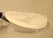
They will still be functional. Mix 25 g of PDMS with 2.5 g (10%) hardening agent and pour it into the dish (Figure 2).  Place on a hot plate at 50 degrees Celsius and cure for 4 h.

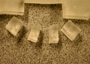
4. Remove the dish from the hot plate and let cool for 5 min.  Using the knife cut the PDMS around the edges of the dish to loosen it.  Then pry the PDMS from the dish (Figure 3).


Figure 3.

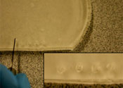
5. Take the 16 gauge blunt needle and place it on the surface of the PDMS.  Turn the needle back and forth while applying pressure to create a through-hole.  Make several holes in a row (Figure 4).


Figure 4.

6. Take the knife and cut squares around each of the holes.  After cutting out the row, each hole can then be separated into individual connectors (Figure 5).

Figure 5.

7. Clean the surface of your microfluidic device with some ethanol.  (The surface must be clean for good adhesion.)  Peel the adhesive off the bottom of the PDMS connector. This should remove the PDMS core made with the blunt needle. If not, you may need to remove it with fine tweezers.

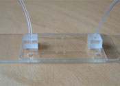
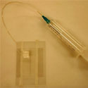
8. Attach the connector to your microfluidic device.  Insert tubing into the connector and attach the other end to a fluidic source such as a syringe (Figure 6).

Figure 6.

Digg This
Reddit This
Stumble Now!
Share on Facebook
Bookmark this on Delicious
Share on LinkedIn
Bookmark this on Technorati
Post on Twitter
Google Buzz (aka. Google Reader)