Archive for the ‘Interfacing and integration’ Category

Wall plug inspired connectors for macro to microfluidic interfacing

Lorenzo Capretto1, Stefania Mazzitelli2, Stefano Focaroli2 and Claudio Nastruzzi2
1 School of Engineering Sciences, University of Southampton, UK
2 Department of Chemistry and Technology of Drugs, University of Perugia, Perugia, Italy

Why is this useful?


Common ways to link microdevices with standard fluidic equipments (such as syringe or peristaltic pumps) are based on the use of nanoports, created by: hand screwing a tube in the substrate material, gluing the tube fitting directly on the microfluidic device or commercial nanoports.
However, when such types of connection are used, there might be a series of potential issues, including: possible leakage of liquid from the connections, especially when high pressure inlet are required, possible clog of the port when glue is used or the high cost of the commercial devices.
Here, we demonstrate an easy and effective way for the creation of cheap and tight microfluidic connection ports for a varied range of substrate material including glass, silicon and polymers. Our approach solves the issues reported above with the creation of and inexpensive, well tight and glue-free port based on a “wall plug inspired” effect.

What do I need?


  • Plastic tube (ETEF, FEP or PTFE) 1/16″ OD, 0.75 mm ID [1]
  • 21 gauge hypodermic needle [2]
  • Drilling bit 1.5 mm [3]
  • A Proxxon, table top, micro miller [3] or any other handheld power tool
  • A cutting disc made of a hard abrasive [3] or any other tool for cutting the needle


Fig. 1.  Tubing used for the production of “wall plug inspired” connectors for macro to microfluidic interfacing: FEP (fluorinated ethylene-propylene) tube (A) and hypodermic needle with Luer-Lock (21 gauge) (B).


Fig. 2. Stereo photomicrographs of the FEP tube (A), the hypodermic needle (B), the hypodermic needle inserted into the FEP tube (C) and the bit used for drilling the microfluidic chips (D). Note the different (crucial) sizes as determined by photomicrograph analysis. External diameter of the FEP tube: 1.58 mm (red arrow); internal diameter of the FEP tube: 0.76 mm (magenta arrow); external diameter of the 21 gauge needle: 0.82 mm (yellow arrow); external diameter of the FEP tube after insertion of the hypodermic needle: 1.66 mm and finally, diameter of the bit used for drilling the microchips: 1.5 mm (white arrow).

What do I do?


1. First drill the hole on the microfluidic device you wish to connect.


Fig. 3. Drilling process on different materials, namely: commercial TOPAS® COC (A) and custom made poly(methyl methacrylate) (PMMA) (B) or epoxy resin (C) chips.

2. Cut the needle and pre-insert it in the plastic tube.


Fig. 4.  Assembly of the”wall plug inspired” connectors. Cutting (A), sanding (B) and insertion (C) of the needle into the FEP tube.

3. Assemble the port and tighten it in the previously drilled hole by inserting the needle in the tube. The needle must be inserted deeper than the interface between tube and hole in order to leverage the wall plug effect.


Fig. 5.  Insertion of the finished “spit inspired nanoport” into different chip type, namely: commercial TOPAS® COC (A) and custom made epoxy resin (B) or polydimethylsiloxane (PDMS) (C) chips


Fig. 6. Schematic representation of the assembling of “wall plug inspired” microfluidic ports.

References


[1] http://www.upchurch.com
[2] http://www.artsana.com
[3] http://www.proxxon.com

Digg This
Reddit This
Stumble Now!
Share on Facebook
Bookmark this on Delicious
Share on LinkedIn
Bookmark this on Technorati
Post on Twitter
Google Buzz (aka. Google Reader)

Quick-connect tubing adapters with small dead volume

Gregory A Cooksey1 and Glynis Mattheisen2

1 Biochemical Science Division, National Institute of Standards and Technology, Gaithersburg, MD
2 Louisiana State University, Baton Rouge, LA

Why is this useful?


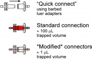
Luer adapters are convenient tools to rapidly and reversibly connect tubing from fluid reservoirs to microfluidic devices. One problem associated with the use of these adapters is that they trap considerable dead volume (approx 100 µl), which dramatically increases the time required to rinse away one fluid when another fluid is to be delivered down the same line. Another common shortcoming of leur adapters is that they are only available for 1.59 mm (1/16″) and larger inner diameter (ID) tubing. We demonstrate how to modify luer adapters to fit almost any size tubing while dramatically reducing the dead fluid volume trapped inside the connector.

What do I need?


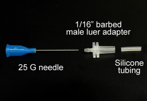
  • 25 mm or longer needle or stainless steel tubing.  We use blunt 25 gauge needles (McMasterCarr # 75165A761). Use extreme care with exposed needles!
  • Polypropylene 1/16 in. barbed male luer adapter (Cole Parmer #R-45503-07)

  • Silicone tubing with large enough ID to slip over needle but small enough outer diameter (OD) to fit inside luer adapter.  We use 0.8 mm ID silicone tubing (Cole Parmer #R-06411-60)
  • Poly(dimethylsiloxane) (PDMS) (Sylgard 184, Dow Corning)
  • Tubing to attach to the connectors.  We use 0.51 mm ID tygon microbore tubing for 25 gauge needles (Cole Parmer #R-06418-02)
  • Dremel 300 (Dremel) or similar tool with cutoff wheel (Dremel #409)

How do I do it?


1. Insert the needle into the barbed end of the 1/16 in. barbed male luer adapter.
2. Thread about 15 mm of silicone tubing onto the needle and push the tubing to the base of the adapter using tweezers.  This keeps the needle centered in the adapter, and the silicone tubing bonds well to the PDMS.  The tubing should stick out of the adapter about 3mm, which accounts for extra dead space that exists in needle hubs and other female luer adapters.
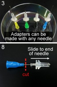
3. Place the hubs of the needles you’ve made onto a dish standing upright.  Double-sided tape on the bottom of the dish will help keep the needles upright.
4. Fill the inside of the luer adapters with PDMS.  We find it helpful to use a syringe (with an 18 G needle) to inject PDMS into the adapters.  At this point it is recommended to de-gas the PDMS by placing it in a vacuum jar for several minutes.
5. Place the dish in an oven at 70ºC to cure for at least 2 hours.  Check after about an hour to make sure the luer hubs stayed filled with PDMS.  You may have to add some additional PDMS if some has leaked out the barbed end.
6. Remove the needle from the dish and clear away excess PDMS from the base of the needle and the outside of the adapter.
7. Push the adapter to the tip of the needle.
8. Cut away the needle luer hub.  A wire cutter can be used, but we prefer using a Dremel tool fitted with a cutting wheel.  It is less likely to compress the tubing closed.  Polishing the end of the needle with the cutting wheel is also recommended.
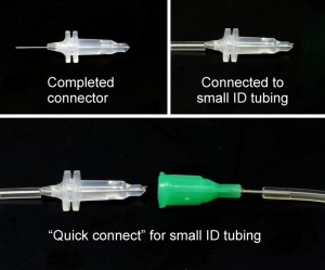
9. Insert the needle extending from the barbed end of the adapter into 0.51 mm ID Tygon tubing.

What else should I know?


“Quick connects” for the same or different ID tubing can be made by plugging the connector into the luer hub of a blunt needle that fits tightly inside the desired tubing.

We have also tried filling the luer hubs with PDMS and curing them prior to inserting needles or stainless steel tubing.  Because the needles are flexible, we find it difficult to keep the needles straight through the center of PDMS core.  This method also typically plugs the needle, so a new needle would be necessary to replace the coring needle.

Disclaimer: Certain commercial equipment, instruments or materials are identified in this report to specify adequately the experimental procedure. Such identification does not imply recommendation or endorsement by the National Institute of Standards and Technology, nor does it imply that the materials or equipment identified are necessarily the best available for the purpose.

Digg This
Reddit This
Stumble Now!
Share on Facebook
Bookmark this on Delicious
Share on LinkedIn
Bookmark this on Technorati
Post on Twitter
Google Buzz (aka. Google Reader)

Connector-less manipulation of small liquid volumes in microchannels

Christopher Moraes, Yu Sun, and Craig A. Simmons
Department of Mechanical and Industrial Engineering, University of Toronto, Toronto, Ontario, Canada

Why is this useful?


An often-touted advantage of microfluidic systems is the small volumes of reagents required.  However, the world-to-chip interconnects often require fluid volumes orders of magnitude greater than those used within the microfluidic channels themselves.  Moreover, commonly used interconnect schemes are either expensive; custom-manufactured or require substantial additional fabrication efforts; or are severely prone to failure, leaks and clogging.

This tip presents a simple, inexpensive and easily-accessible method to manipulate small volumes of fluid in standard microfabricated PDMS channels, without the use of a connector scheme.  Though it cannot be used to produce well-controlled or continuous long-term flow, we have found it ideal for applications such as device pre- and post-processing (e.g., chemical-based surface modification and immunostaining).  The technique is simple and robust, and has been used effectively both by experienced researchers and untrained, minimally supervised undergraduate students in a teaching lab.

What do I need?


  • Fully cured microfluidic PDMS device
  • Glass substrate
  • PDMS punch
  • 1 mL Pasteur pipette bulb (Sigma-Aldrich, product Z111589)
  • Pipettes and tips
  • Kimwipes

Figure 1

How do I do it?


1. Punch an access port into the PDMS device at the channel entry and exit points.  The size of the hole can be selected based on the reagent volume required by the device.  In this example, we used a 1/8″ diameter punch.

2. Bond the patterned PDMS layer to a glass slide, as per standard procedure for PDMS device fabrication.

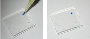
3. Pipette a small quantity of reagent directly into the access port (Figure 1; blue dye used for this demonstration).  We have successfully used this technique with volumes as low as 4 mu.gifL.

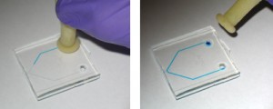
4. Place the Pasteur pipette bulb (Figure 2) over the punched reservoir and gently hold it down so it forms a conformal seal around the reservoir (Figure 3).  Provided the area around the access port is fairly flat, maintaining a seal is typically not a problem.

Figure 2

Figure 3

5. Squeeze the bulb gently to apply positive pressure and cause the fluid to flow into the microchannels (Figure 4).

Figure 4

6. Channels can be cleared by first pipetting away excess fluid from the access port, and then using the Pasteur pipette bulb to force air through the channel, while wicking away the expelled liquid at the exit port with a Kimwipe.

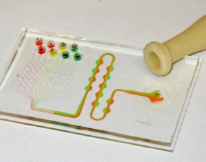
The Pasteur pipette bulb can also be used to apply a negative pressure by squeezing it first, placing it over the channel access port, and gently releasing the bulb.  In Figure 5, we used this technique to drive flow in a standard microfluidic gradient generator system:  negative pressure is applied at the outlet channel port, drawing eight separated reagents through the mixing channels.

Figure 5

Digg This
Reddit This
Stumble Now!
Share on Facebook
Bookmark this on Delicious
Share on LinkedIn
Bookmark this on Technorati
Post on Twitter
Google Buzz (aka. Google Reader)

Simple, low-cost, low-temperature cured adhesive rings for microfluidic ports

Johnny J. Perez and Jonathan G. Shackman
Department of Chemistry, Temple University, Philadelphia, PA, USA 19122

Why is this useful?


A critical step in fabrication of microfluidic devices is coupling with the macroscopic world.  Reservoirs or pressure fittings are frequently adhered to devices by liquid epoxies or heat cured adhesive rings, such as supplied with commercial Upchurch Scientific (Oak Harbor, WA, USA) NanoPorts.  Liquid methods can potentially enter the device and clog channels.  Non-tacky resin rings make alignment of critical fittings and O-rings difficult, as they are inert until heat cured.  As an alternative to PDMS-based interfacing [1,2,], we describe a simplified method for forming customized, tacky adhesive rings using 3MT VHBT pressure-sensitive tape (Fig 1).  The rings are similar to the now discontinued NanoPort rings formed from 3MT 583 tape [3], but can cure at room temperature.  We have tested NanoPorts using these rings underwater on both polycarbonate and glass substrates in excess of 40 psi with no failures.  The cost per ring (assuming a 1 cm diameter) is a few US pennies.  Rings can easily be peeled from the ports and substrate after applying sufficient torque or sheer forces without leaving residues, facilitating aggressive cleaning (such as in piranha solution) of clogged microchannels.

Figure 1

What do I need?


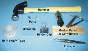
The materials needed are shown in Figure 2 and include:

  • 3MT VHBT tape.  We use 0.5″ wide VHBT 4926, but a variety of tapes (including 3MT 583 tape) could be used, with selectable adhesion qualities and solvent resistances.
  • Gasket Punch or Cork Borers.  Cork borers (commonly used in chemistry labs) require two cuts while dual cutting punches, such as available from McMaster-Carr (Elmhurst, IL, USA), cut both inner and outer rings simultaneously.  We use 3/16″ inner and 7/16″ outer diameter punches for NanoPort rings.
  • Hammer and pad.  A piece of scrap wood can be used for a cutting pad.
  • Forceps.  Fine tips aid in ring manipulation and removing the adhesive backing.
  • Ports and microchip.  Homemade or commercial ports and chips can be used with the method.  The glass device used for demonstration was made using previous protocols [4].
  • Binder clip.  The tape requires at least 10 psi for strong bonds and pressure should be maintained during curing.  Mini-vises or C-clamps can also be used for hard to reach ports [3].
  • Oven (optional).  VHBT tape can cure overnight at room temperature or in 1 hr at 60 to 90 °C.

Figure 2

What do I do?


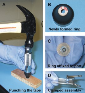
The sequence is shown in Figure 3.  The following specifics can easily be modified for a given application.

Figure 3

1. Clean ports / O-rings in DI water followed by methanol or isopropanol.  It is assumed the microdevice is clean after fabrication but can also be carefully cleaned.
2. Cut a 1 cm length of tape and place the sticky side on the punch.
3. Place the end of the punch/tape on a pad or wood block and hit the opposite end of the punch with a hammer (Fig 3A).
4. The ring will likely remain in the punch, with the backing side facing out (Fig 3B).  Use forceps to remove the newly formed ring and attach the exposed tacky side to the port.  Pressing the port (prior to removing the backing) against a flat surface can help adhesion.
5. Remove the backing with forceps to expose the other tacky side (Fig 3C) and align the assembly with the microchip access hole.
6. Clamp the port and microfluidic device using a binder clip or clamps (Fig 3D).
7. Cure either overnight or for 1 hr in an oven at 60 to 90 °C.
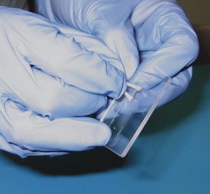
8. Adhered ports can be removed by either twisting and tilting or tightening a nut longer than the port to lift the port off the substrate.  The remaining ring can be removed using forceps to lift an edge and peeling (Fig 4).

Figure 4

What else should I know?


Rings should be made as needed to prolong shelf life (VHBT on the roll lists a 2 yr life when stored at room temperature and 50% relative humidity) [5].  While suitable for aqueous solutions, prolonged use of organic solvents is not recommended with VHBT tape [6], and an alternative adhesive or method, such as described by Watson and Wheeler [1], is suggested.  Application of high torque will cause the rings to fail, as can occur when over-tightening pressure fittings.

References


[1] M. W. L. Watson, A. R. Wheeler, Organic solvent compatible reservoirs for glass microfluidic chips, Chips & Tips, (Lab on a Chip), 12 December 2007
[2] J. Greener, W. Li, D. Voicu, E. Kumacheva, Reusable, robust NanoPort connections to PDMS chips, Chips & Tips, (Lab on a Chip), 24 October 2008
[3] C. Koch, J. Ingle, V. Remcho, Bonding Upchurch® NanoPorts to PDMS, Chips & Tips, (Lab on a Chip), 15 February 2008
[4] N.I. Davis, M. Mamunooru, C.A. Vyas, J.G. Shackman, Anal. Chem., 2009, 81, 5452-5459.
[5] 3MT VHBT Double Coated Acrylic Foam Tapes – June 2009 Data Sheet
[6] 3MT VHBT Durability – March 2001 Bulletin

Digg This
Reddit This
Stumble Now!
Share on Facebook
Bookmark this on Delicious
Share on LinkedIn
Bookmark this on Technorati
Post on Twitter
Google Buzz (aka. Google Reader)

Reversible high contact bonding of microscope slide chips

Jian Hua Han, Shao Hua Li, Zhong Han Sheng and Long Jiang
Key Laboratory of Colloid and Interface, Institute of Chemistry, Chinese Academy of Sciences (ICCAS), Beijing, China

Why is this useful?


We demonstrate a reversible bonding method to fabricate microscope slide glass chips. This method involves pre-curing a PDMS polymer layer to form a highly adhesive glue which strongly bonds glass chips. Traditional bonding methods[1-4] are either irreversible or not very strong; our approach solves this problem. The glass chips made by our approach can bear high fluid pressure without leakage and can easily be disassembled and reassembled when clogging happens. Our method is suitable for any ordinary labs that lack expensive equipment to fabricate microfluidic chips.

What do I need?


  • Microscope slides and PDMS kits (SYLGARD®184), produced by Dow Corning. The silicone elastomer base and curing agent were mixed well at the ratio of 10:1 to form a paste before use.
  • Craft knife, scalpel, plastic wrap, etc.
  • Microscope slides chip with patterns and appropriately located inlet and outlet holes.

What do I do?


First, prepare a microscope slide chip using standard wet etching methods[5] and drill holes. Then execute the following 5 steps:

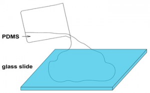
1. Pour the PDMS (elastomer mixed with curing agent and degassed) onto a glass slide, see figure 1.

Figure 1

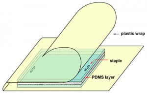
2. Place another glass slide onto the PDMS of step 1 carefully, avoiding any bubbles during the process. Use a staple as a spacer, and wrap the sandwich in plastic wrap to avoid leakage of PDMS. See figure 2.

Figure 2

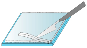
3. Cure the PDMS to a solid state, then pry up the upper slide. Use a scalpel to trim the PDMS layer to size, see figure 3.

Figure 3

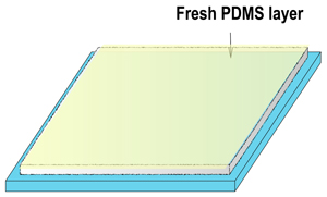
4. Spin coat a fresh PDMS layer 1µm thick onto the PDMS layer of step 3 at the rate of 3000 RPM, then pre-cure for 20min at 80°C to form a hard glue, see figure 4.

Figure 4

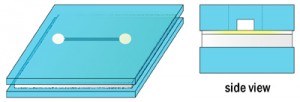
5. Place the glass slide chip (with patterns and appropriately located inlet and outlet holes) onto the PDMS layer of step 4, then continue to cure the polymer to a solid state, and the microfluidic chip is formed, see figure 5.

Figure 5

What else should I know?


The method presented above is a useful method for rapid fabrication of microfluidic chips. The advantages of this method are as follows:

  • does not need a strictly flat surface, very cheap microscope slides are available
  • high contact bonding strength, does not rupture under high pressure (280kPa), while commonly used devices cannot withstand fluid pressures of more than 100kPa
  • the chip can be opened with a craft knife when clogging happens and can be reused many times

The limitation of this method is that you must be careful when placing the etched glass slide onto the uncured PDMS layer – avoid too much pressure on it since this could lead to squeezing of PDMS into the channels and clogging of the chip.

Acknowledgements


This research is funded by the Chinese Academy of Sciences (grant number KJCX2-YW-H18) and the National Sci-Tech Special Item for Water Pollution Control and Management (2009ZX07 5287- 007 – 03).

References


[1] N. Miki, Sensor Letters, 2005, 3, 263-273
[2] A. Sayah, D. Solignac, T. Cueni and M. A. M. Gijs, Sensors and Actuators A: Physical, 2000, 84, 103-108
[3] S. Shoji, H. Kikuchi and H. Torigoe, Sensors and Actuators A: Physical, 1998, 64, 95-100
[4] N. Chiem, L. Lockyear-Shultz, P. Andersson, C. Skinner and D. J. Harrison, Sensors and Actuators B: Chemical, 2000, 63, 147-152
[5] M. Castano-Alvarez, D. F. Pozo Ayuso, M. Garcia Granda, M. T. Fernandez-Abedul, J. Rodriguez Garcia and A. Costa-Garcia, Sensors and Actuators B: Chemical, 2008, 130, 436-448

Digg This
Reddit This
Stumble Now!
Share on Facebook
Bookmark this on Delicious
Share on LinkedIn
Bookmark this on Technorati
Post on Twitter
Google Buzz (aka. Google Reader)

Easy and reversible connection with patafix for a pressure flow control system

Ayako Yamada, Fanny Barbaud, Yong Chen, and Damien Baigl
Department of Chemistry, Ecole Normale Superieure, Paris, France

Why is this useful?


Controlling flows in a microfluidic channel by gas pressure is sometimes preferable due to the stability and quick response of flows. Here we describe an easy way of connection between a sample reservoir and tubing connected to a pressure regulator without gas leakage. With our tips, one can quickly prepare a sample reservoir; one can easily open and close it to refill during experiments; one can easily disassemble, clean, and reuse the system, if necessary. It is also possible to manage a small volume sample (e.g., 5 µL) by employing a micropipette tip.

What do I need?


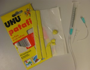
1. Patafix from UHU GmbH & Co. KG (Baden, Germany)
2. Plastic syringe without plunger (for a large volume sample; e.g., 100 – 1000 µL)
3. Needle for the syringe without pointed tip (for a large volume sample; e.g., 100 – 1000 µL)
4. Micropipette filter tip (for a small volume sample; e.g., 5 µL)
5. Tubing
6. Compressed air
7. Pressure regulator
8. PDMS channel


For a large volume sample (e.g., 100 – 1000 µL)


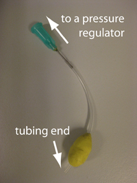
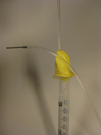
1. Wrap patafix around tubing to make a ball of approximately 1.5 cm diameter, leaving 5 mm from the tubing end (Fig. 1). The other end is to be connected with a pressure regulator. Put suitable accessories for your system.

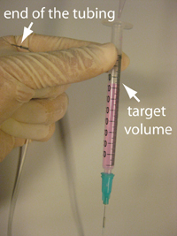
2. Connect a plastic syringe, a needle, and tubing. Hold the other end of the tubing, which is to be connected with your microfluidic channel, higher than the target volume in the syringe. Then fill the syringe with your sample using a micropipette (Fig. 2). Remove air bubbles by tapping, if necessary.

Figure 1

Figure 2

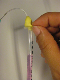
3. Insert the tubing with patafix prepared in step 1 to the open part of the syringe. Then squeeze the patafix into the syringe with your fingers so that about 5 mm of the syringe becomes filled (Fig. 3).

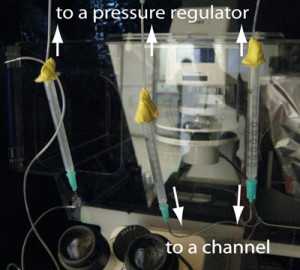
4. You can keep the tubing end accesible by sticking it on the patafix ball (Fig. 4). Connect the syring tubing to the pressure regulator keeping the syringe vertical. Following this way, your sample never touches patafix. It is convenient to place the pressure regulator high enough so that you can hang up the syringe from the regulator and maintain it vertical.

Figure 3

Figure 4

5. Connect the tubing with your channel and apply pressure (Fig. 5). This system can withstand operating pressures up to about 700 mbar (gauge pressure). You can open it by pulling the patafix out of the syringe, and easily refil with the sample, if necessary. If the tubing end is buried in patafix, simply tear off patafix until the tubing end appears. It is better not to try to dig patafix. It makes patafix go inside the tubing.

Figure 5

For a small volume sample (e.g., 5 µL)


1. Same as the step 1 described above, except that the diameter of the patafix ball should be about 2 cm.

2. Take your sample by micropipette. A pipette tip with a filter is preferable.

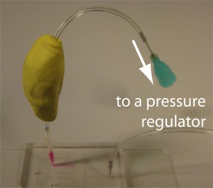
3. Remove the tip from the micropipette. If air comes up into the tip, you can get rid of it by tapping the tip gently until your sample goes back to the tip end. Then insert the tip into a PDMS channel inlet (we make inlet holes by punching through the PDMS with a syringe needle without a pointed tip and cleaning with isopropanol) (Fig. 6).

Figure 6

4. Connect the tubing and patafix prepared in the step 1 with the pipette tip. Try to make a homogeneous thickness (about 5 mm) layer of patafix around the connection and seal well (Fig. 7). Connect them to the pressure regulator and apply pressure. This system can withstand operating pressures up to about 300 mbar (gauge pressure).

Figure 7
Digg This
Reddit This
Stumble Now!
Share on Facebook
Bookmark this on Delicious
Share on LinkedIn
Bookmark this on Technorati
Post on Twitter
Google Buzz (aka. Google Reader)

“Custom made” production of cheap Luer lock adapters for chip-to-syringe interfacing

Stefania Mazzitelli, Stefano Focaroli and Claudio Nastruzzi
Department of Chemistry and Technology of Drugs, University of Perugia, Perugia, Italy

Why is this useful?


One of the standard procedure to pump solutions, emulsions or suspensions, into microfluidic chips is based on the use of syringes, through peristaltic pumps. Syringe pumps are usually preferred over peristaltic ones, for their ease of use, for the accurate and stable control of the flow rate and, finally, for the possibility to employ sterile conditions.

Luer taper is a standardized system of small-scale fluid fittings used for making leak-free connections between a male-taper fitting and its mating female part on medical and laboratory instruments, including hypodermic syringe tips and needles or stopcocks and needles. The fitting is named after the 19th century German medical instrument maker Hermann Wülfing Luer.

There are two varieties of Luer Taper connections: Luer-Lok and Luer-Slip; Luer-Slip fittings simply conform to Luer taper dimensions and are pressed together and held by friction (they have no threads). Luer components are manufactured either from metal or plastic and are available from many companies worldwide but they are usually sold in few standard dimensions and are relatively expensive.

In this Tip we present a way to easily produce a variety of “on demand” Luer connectors, including: (a) female Luer x female Luer adapter, (b) female Luer x female Luer elbow, (c) male Luer x male Luer adapter, (d) male Luer x male Luer elbow, (e) male Luer x female Luer coupler and finally (f) male Luer x female Luer elbow.

What do I need?


  • 1-30 mL polypropylene syringes (Artsana, Italy) [1]
  • tubing: Upchurch Scientific® FEP (fluorinated ethylene-propylene); Tub FEP Nat 3/16 x .125 x 20ft (Upchurch Scientific, UK; No.: 1524) [2]
  • tubing: Timmer-Pneumatik GmbH; H-PTFE-4/2 mm (OD/ID)-blue, catalog Timmer 2001 [3]
  • Aesculap scalpel blades fig. 23, carbon steel, package of 100 pieces in dispenser package [4]
  • Aesculap scalpel handle fitting no. 4 for blades 18-36, 135 mm, 5 ¼, [5]
  • Black & Decker heat gun, model kx1693, [6]

What do I do?


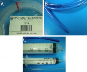
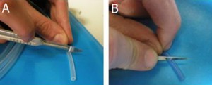
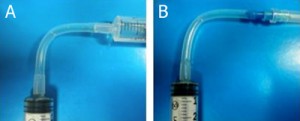
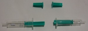
1. Tubing (A, B) and template syringes (C) are used for the production of Luer connectors. A: FEP (fluorinated ethylene-propylene) tubing; B: H-PTFE tubing.

Figure 1

2. Tubing cutting by scalpel. The length of the Luer connector can be adjusted depending on the specific needs of the researcher (for instance, the distance between the syringe pump and the chip). Note that in the case of H-PTFE tube (B), the cutting is made with an angle of 45° with respect to the tube major axis.

Figure 2

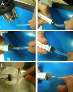
3. Preparation of a female Luer adapter: A. Heating of a FEP tube end by heat gun for 1-3 min; B-D. Press and insert the male Luer of a polypropylene syringe into the heated tube. E. Cool down the tube by tap water. F. Permanent deformation of the tube end.

Figure 3

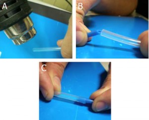
4. Preparation of a male Luer adapter: A. Heating of a FEP tube end by heat gun for 1-3 min; B-C. Press and insert the H-PTFE tube end (cut at 45°) into the heated FEP tube, cool down the tube connection by tap water until a permanent deformation is reached.

Figure 4

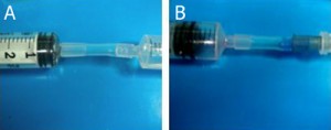
5. Examples of female Luer X female Luer adapter (A) and female Luer X male Luer adapter (B).

Figure 5

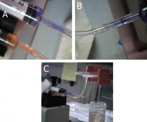
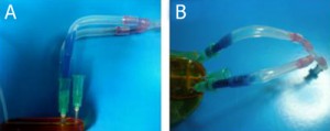
6. Examples of female Luer X female Luer elbow (A) and female Luer X male Luer elbow (B).

Figure 6

7. Examples of the use of female Luer X female Luer adapter to connect syringes to a commercial chip.

Figure 7

8. Examples of the use of female Luer X male Luer elbow to connect syringes to a homemade chip.

Figure 8

References


[1] http://www.artsana.com
[2] http://www.upchurch.com
[3] http://www.pneumatica-it.timmer-pneumatik.de
[4] http://www.chirurgische-instrumente.info/en/search.html?kw=bb523
[5] http://www.chirurgische-instrumente.info/en/search.html?kw=bb084r

Digg This
Reddit This
Stumble Now!
Share on Facebook
Bookmark this on Delicious
Share on LinkedIn
Bookmark this on Technorati
Post on Twitter
Google Buzz (aka. Google Reader)

Plug-and-play reservoirs for microfluidics

Christopher Y. Wong*, Georgian Ionut Ciobanu*, Mohammad A. Qasaimeh, and David Juncker
Micro and NanoBioEngineering Laboratory, Biomedical Engineering Department, Faculty of Medicine, McGill University, Montreal, Canada.
* Authors contributed equally

Why is this useful?


Microfluidic and lab-on-a-chip (LOC) devices are typically connected to external sample reservoirs. A significant issue for LOC devices is interfacing multiple sample reservoirs and connecting them both to external pressure controllers or syringe pumps and to the microfluidic chip [1,2]. Researchers typically use home-made reservoirs and interfacing them to the chip and the controllers requires specialized skills and training and/or additional fabrication steps.[3,4] Often the connections are unreliable and leaky, and as a consequence much time is lost in setting them up and it is difficult to add or remove connections from the reservoirs.

Here we introduce a “plug-and-play” reservoir that allows for multiple connections to be simply plugged in. The reservoirs are made using off-the-shelf threaded microcentrifuge tubes and screw-on septum caps. Needles, capillaries and steel tubing can be inserted one at a time – or in combination – through the cap’s septum and used to connect the reservoir to a pressure source and to one or several inlets of a microfluidic chip. The connectivity between reservoir and pressure source(s) and chip(s) can be adapted to specific needs, for example to form a reservoir with a single input and a single output, or with multiple inputs and outputs. Reservoirs with single or multiple input/output lines can be switched easily by by unscrewing the microcentrifuge tube and screwing the cap with the capillaries on another microcentrifuge tube containing a different solution.

The reservoirs are cheap, disposable, easy to assemble, and robust enough to support pressures up to 345 kPa (and even higher pressures with the variant described in the supplementary material) while having almost no dead volume. The connection of reservoirs to microfluidic chips – or to other reservoirs so as to form complex circuits – can be performed in a matter of seconds. Arrays of off-chip reservoirs can be assembled within racks and many lines can be connected at high density to a microfluidic chip. These plug-and-play reservoirs are a versatile solution to the world-to-chip interface and should find widespread application for microfluidic experimentation.

What do I need?


For the reservoir:

  • threaded screw cap with membrane/septum [5]
  • threaded microcentrifuge tube (any volume, as long as it has the same thread type as the cap) [5]

For the connections:

  • sharp hypodermic needle with Luer-Lock (any size from 23 to 16 gauge) [6]
  • 1/16″ ID Tygon tubing or other preferred tubing [7]
  • male Luer-lock to 1/16″ ID hose barbed tubing adapters [7]
  • glass capillary (Note: OD of glass capillary needs to be smaller than ID of needle) [8]

Optional for other connection types (shown in supplementary materials):

  • 0.0250″ OD hollow steel tubing [9]
  • 0.0200″ ID microbore Tygon Tubing [10]

Fig. 1 shows the required parts. Fig. S1 in the supplementary materials shows the alternative options in our laboratory of microcentrifuge tube sizes and input/output connection types. (A) Threaded screw cap with membrane/septum [5]. (B) Threaded microcentrifuge tube [5]. (C) Sharp 20G1½ hypodermic needle with Luer-Lock [6]. (D) 1/16″ ID Tygon tubing [7]. (E) Male Luer-lock to 1/16″ ID hose barbed tubing adapter [7]. (F) Glass capillary of 350 µm OD [8].
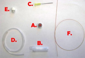
Figure 1. Different parts used to make the reservoir.

What do I do?


1. In order to insert a glass capillary to serve as an output, use a sharp hypodermic needle with an inner diameter (ID) that is just larger than the capillary’s outer diameter (OD). Insert the needle into the membrane screw cap and then slide the capillary through the needle, as shown in Fig. 2.

Figure 2. Insert a needle into the membrane screw cap and pass the glass capillary through the needle.

2. Screw the cap onto a reservoir of the desired size and then remove the needle while holding the capillary in place, as shown in Fig.3. Repeat steps 1 & 2 for every additional glass capillary connection required.

Figure 3. Pulling the needle out but keeping the capillary in place fixed by the membrane.

3. Insert the input pressure needle to appropriate depth (see next section for details) and connect to the Tygon tubing to the needle using the Luer-lock to tubing adapters, as shown in Fig.4. Repeat this step for every additional Tygon tubing connection required.

Figure 4. Reservoir with a needle connection interfaced to a glass capillary (typically connected to the microfluidic chip) and Tygon tubing with a Luer-lock adaptor (typically connected to the pressure source) which can be used to control the flow from the reservoir to the chip.

4. The reservoir is completed. Unscrew the cap from the container and fill it with your reagent and screw the cap back on.

5. (Optional step) Instead of using a glass capillary, a steel tube connected to Tygon microbore tubing can be used. We used 0.0250″ OD steel tubing, inserted into 0.0200″ ID Tygon tubing and then forced the pin through the septum, as seen in Fig. 5. Multiple steel-Tygon tubing connections can be connected to one septum as shown in Fig. S2.

Figure 5. Steel tubing and Tygon microbore tubing connected to a reservoir.

6. Connect the 1/16″ Tygon tubing to the pressure source and the capillary (or the microbore Tygon tubing) to the chip. Make sure to create slightly smaller sized holes for the input connections on the chip to create a tight seal. When using multiple reservoirs, they can be placed into microcentrifuge tube racks for easy handling (Microtube Storage Racks), as shown in Fig. 6.
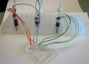
Figure 6.  A picture of a chip connected to three reservoirs placed on a storage rack, each with an independent input line and multiple outputs.

7. Everything is now ready to use!

What else should I know?


This setup is simple, easy to build and can be done in less than a minute. Depending on the cap, the membrane/septum provides an airtight seal, but after inserting and removing needles more than a few times, especially with larger needles, leakage becomes apparent. Since the system is pressure controlled, a small leakage rate relative to the supply flow rate can be tolerated. Only a limited number of connections, up to 10 in our experience, can be connected to a single cap or else leakage becomes excessive. The reservoirs work well up to 345 kPa, and for higher pressure applications solid caps can be used as described in the supplementary material.

It is important to maintain the needle connected to the pressure source above the liquid surface in order to prevent the formation of bubbles. Be careful of the sharp points and remember to dispose of the needles properly.

Supplementary materials
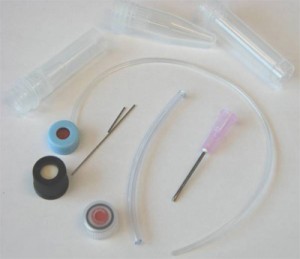

Figure S1. The different available options (excluding glass capillaries) in our laboratory of microcentrifuge tubes sizes, membrane caps, steel tubing, and input/output connections.
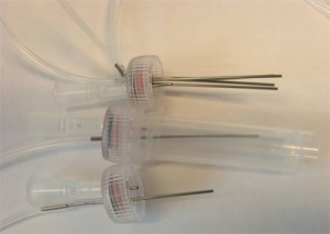
Figure S2. Multiple tubing outputs through multiple inserted steel tubing.

The presented setup above was not tested at pressures higher than 345 kPa, and at pressures above 140 kPa, there was minimal gas leakage. However, we have developed another setup that works without any leakage, even at 345 kPa, but requires several minutes to make and a precision micro-drill. This setup does not use a membrane cap, but a conventional screw cap without a membrane. Using suitable micro-sized drill bits, different sized holes can be made in the micro tube or the cap. After inserting the output capillaries or steel tubing and the input syringe needle, Instant Krazy glue [10] is applied to affix the inputs and outputs at the precise place. Dual melt glue [11] is then applied to seal the terminals from air/liquid leaks. The final setup is shown in Fig. S3.

We mention here that this setup is permanent and should be robust at high pressure applications. At the same time, it requires a precision micro drill, more time to make, and it is less flexible in the sense that it is harder to modify the interface.

Figure S3. High pressure off-chip containers with one Luer-Lock input and one glass capillary output at the bottom.

References


[1] S. Li and S. Chen, IEEE Trans. Adv. Packag., 2003, 26, 242-247.
[2] R. Lo and E. Meng, Sens. Actuators, B, 2008, 132, 531-539.
[3] T. Liu, E. V. Moiseeva and C. K. Harnett, Integrated reservoirs for PDMS microfluidic chips, Chips & Tips (Lab on a Chip), 22 April 2008.
[4] T. Das et al., Interfacing of microfluidic devices, Chips & Tips (Lab on a Chip), 27 February 2009.
[5] Sarstedt AG & Co.: http://www.sarstedt.com/
[6] BD: http://www.bd.com/
[7] McMaster-Carr Supply Company: http://www.mcmaster.com/
[8] Polymicro Technologies: http://www.polymicro.com/
[9] New England Small Tube: http://www.nesmalltube.com/
[10] Small Parts, Inc.: http://www.smallparts.com/
[11] Krazy Glue: http://www.krazyglue.com/
[12] The Stanley Works: http://www.stanleyworks.com/

Digg This
Reddit This
Stumble Now!
Share on Facebook
Bookmark this on Delicious
Share on LinkedIn
Bookmark this on Technorati
Post on Twitter
Google Buzz (aka. Google Reader)

A remote syringe for cells, beads and particle injection in microfluidic channels

Jean-Christophe Baret
Institut de Science et d’Ingénierie Supramoléculaires (ISIS),
Université de Strasbourg, CNRS UMR 7006, Strasbourg, France
jc.baret[at]unistra.fr

Why is this useful?


In suspension, cells, beads and particles tend to sediment at a speed given by the balance of viscous drag and gravity force. In classical biological experiments, the most straight-forward solution to keep cells in suspension is to shake large volumes. This type of system is relevant at high Reynolds number but is not very compatible with the classical systems used to inject small amounts of liquid in confined geometries, such as microfluidic systems.

Another common way to prevent sedimentation is to match the densities of the particles and the carrier fluid, or to increase the viscosity of the carrier fluid to increase sedimentation times. However, these solutions are not always suitable due to the biological or physical constraints of a microfluidic experiment. For example, increasing viscosities increases the pressure drop in microchannels, and additives for density matching are not always biocompatible.

Previously in the Chips and Tips section a system has been described for cell injection [1]. With a similar system, we observed that sedimentation along the tubing binding the syringe reservoir to the chip hinders good mixing of the cells. This tubing should therefore be as short as possible, which is sometimes incompatible with the large footprint of the syringe pumps or other equipment around the microfluidic chip. Interestingly, in another Chips and Tips section, a system for temperature control of syringe pumps has been described [2]. The idea there was to use a syringe pump to pump liquid in order to move the piston of another syringe placed in a temperature-controlled bath. This system still showed problems related to the length of the connection tubing to the chip.

Here we combine both systems [1,2] to inject cells, beads and particles efficiently into microfluidic devices using small amounts of liquids (typically ~1 mL). The cells are initially placed in a syringe close to the chip and are automatically shaken inside the syringe using a small motor and a magnet. This syringe is then remotely actuated by another syringe mounted on a syringe pump [2] which reduces the footprint of the injection system in the vicinity of the chip. The tubing length from the syringe containing the cells to the chip can then be as small as 5 cm, which reduces the residence time of cells in the tubing and therefore reduces sedimentation.

What do I need?


  • Syringes: BBraun Injekt (2 mL or 5 mL)
  • Syringe needles: Terumo NEOPLUS 23G
  • Tubing: Fisher Scientific PTFE tubing (i.d. 0.56 mm, o.d. 1.07 mm)
  • Small magnets: Supermagnete, e.g. S-03-01-N
  • Teflon magnets: Fisher Scientific, length 6 mm, diameter 3 mm
  • Motor: Radiospares, e.g. 20GN steel 50:1 gear DC motor, 175rpm 12V
  • Power supply: Radiospares, e.g. LASCAR – PSU 130
  • Small equipment: stands and support, steel wire

What do I do?


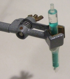
1) The first part of the procedure deals with preparing the syringes. This system is very close to the one presented in [1]. Cut the plungers of 2 syringes, and insert a magnet in one (Fig 1).

2) Bind them together with the metal wire (Fig 2).

Figure 1

Figure 2

3) Fill the syringe that does not contain the magnet with water and hold it vertical (Fig 3).

Figure 3

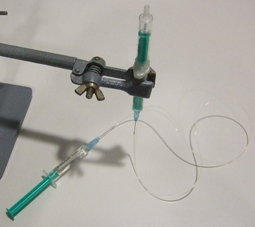
4) Insert the needles in the tubing, fill a third syringe with water, place the needle in position, flush the tubing with water and connect the syringe with the free needle (Fig 4). Make sure no air bubbles are present in the water phase: they will increase the response time of the system to flow rate modifications.

Figure 4

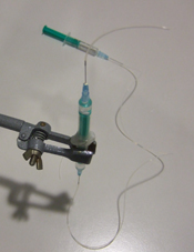
5) Invert the syringe to have the magnet in the upper part and fill this part with the liquid containing the cells, beads or particles (Fig 5) and connect a short needle with tubing (Fig 6).

Figure 5

Figure 6

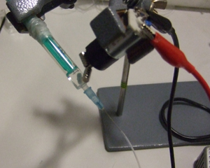
6) Rotate the syringe and mount the motor with the magnets. Turn on the power supply (Fig 7). The speed of the motor is simply controlled by the voltage to guarantee gentle agitation of cells.

Figure 7

7) The system is now ready to be connected to a chip on one hand and to a syringe pump on the other (see video below). More sophisticated systems can probably be adapted to allow a temperature control of the syringe.

References


[1] R. Cooper and L. Lee, Preventing suspension settling during injection, Chips & Tips (Lab on a Chip), 21 August 2007.
[2] L. Capretto, S. Mazzitelli and C. Nastruzzi, An easy temperature control system for syringe pumps, Chips & Tips (Lab on a Chip), 22 April 2008.

Digg This
Reddit This
Stumble Now!
Share on Facebook
Bookmark this on Delicious
Share on LinkedIn
Bookmark this on Technorati
Post on Twitter
Google Buzz (aka. Google Reader)

How to prevent sagging during the bonding or lamination of chips with large aspect ratio chambers

Jie Xu and Daniel Attinger
Laboratory for Microscale Transport Phenomena, Department of Mechanical Engineering, Columbia University, New York, NY 10027, USA

Why is this useful?


Assembling multiple layers by bonding or lamination is a simple way to manufacture complex multilayer microfluidic chips [1, 2].  However, bonding or lamination of chambers with large aspect ratio, i.e. wide and shallow, sometimes fails because of sagging. Figure 1 illustrates a sagging problem, which resulted in the top chamber wall being accidentally bonded to the bottom wall.  Here, we describe a tip to prevent sagging by using regular cooking salt.

Figure 1: Accidental bonding due to sagging

What do I need?


  • Cooking salt (grain size: normally 300 microns, can be further ground to less than 100 micron; melting temperature: 801 °C, good for lamination)
  • Precision tweezers
  • Stereomicroscope

What do I do?


1. Carefully pave the bottom of the chamber with ordinary salt as in Figure 2. Try to perform this action using fine tweezers under a stereomicroscope, if the chamber is too small.

Figure 2

2. Plasma bond or laminate the top layer. Be careful during handling, so that the salt does not end up in your DRIE machine.

Figure 3

3. After bonding is done, flush the microfluidic system with deionized water for several minutes to dissolve and remove salt particles. As figure 4 shows, the bonded chamber does not exhibit adhesion between the top and bottom wall.

Figure 4: No accidental bonding

References


1. J. Xu and D. Attinger, Drop on demand in a microfluidic chip, J. Micromech. Microeng., 2008, 18, 065020.

2. P. J. Hung, P. J. Lee, P. Sabounchi, N. Aghdam, R. Lin, and L. P. Lee, A novel high aspect ratio microfluidic design to provide a stable and uniform microenvironment for cell growth in a high throughput mammalian cell culture array, Lab Chip, 2005, 5, 44-48.

Digg This
Reddit This
Stumble Now!
Share on Facebook
Bookmark this on Delicious
Share on LinkedIn
Bookmark this on Technorati
Post on Twitter
Google Buzz (aka. Google Reader)