Hannah B. Musgrove, Rebecca R. Pompano
Department of Chemistry, University of Virginia
Email: hbm8g@virginia.edu, rpompano@virginia.edu
Why is this useful?
With the continued adoption of 3D printed fabrication for microfluidics, the ability to easily connect non-elastomeric, resin 3D printed devices to fluidic tubing is an ongoing area of optimization. Common strategies to connect tubing to printed chips involve incorporating threading for use with luer lock adaptors, or embedding flanges or O-ring into devices.1–5 While useful for many types of inlets, standard luer adaptors are often > 10 mm in scale and thus too large for smaller chip designs. Additionally, the quality of 3D printed threading depends on the resolution of the printer and resin material, and the threads may wear down with repeated use. Embedding flanges1 or O-rings at connection sites6,7 may alleviate some of these print related limitations and increase the durability of the tubing ports. However, they also require additional manual fabrication steps including gluing or embedding parts and alignment. These extra steps are time-consuming and can increase fabrication inconsistencies. A simple option is to add a tubing-sized hole into a channel design which can be printed easily.6,7 This is similar in concept to dermal punching methods common for polydimethylsiloxane (PDMS)-based chips.1,4 However, while the soft, elastic properties of PDMS allows for a secure connection with tubing-sized holes, most 3D printed materials are more rigid, preventing conformal contact.
To address these issues, we developed a simple, threadless design for a raised port, that produces durable, 3D printed connection sites for tubing. We have used it successfully with both low and high viscosity vat-polymerization 3D printing resins (MiiCraft BV007a and FormLabs Clear, respectively) and compared it with, fused deposition fabrication of the same port using polylactic acid filament. This design is intended to decrease fabrication time and can be used with or without additional commercial adapter parts.
What do I need?
Basic materials are listed first, with the specific tools that we used listed in parenthesis.
- Vat-polymerization 3D printer (MiiCraft P110Y, 385 nm 3D printer)
- Resin (MiiCraft BV007a, or FormLabs BioMed Clear)
- 3D design software (Fusion360 with Education License)
- Microfluidic tubing, 1/16” OD or smaller (1/32” PTFE, 1/32” PEEK, and 1/16” silicon peristaltic tubing)
- Optional: Ferrule lock rings (Idex Super Flangeless Ferrule, Cole-Parmer)
Measurement components for design
- Included 3D software files or blueprint in Figure 1
- Outer diameter (OD) of tubing being used
- Estimate of print shrinkage and tolerance needed
What do I do?
- With 3D designing software, open the design to which you wish to add tubing
 connection ports.
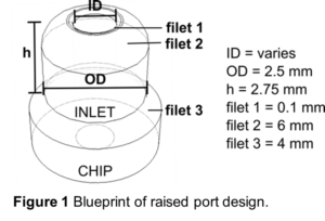
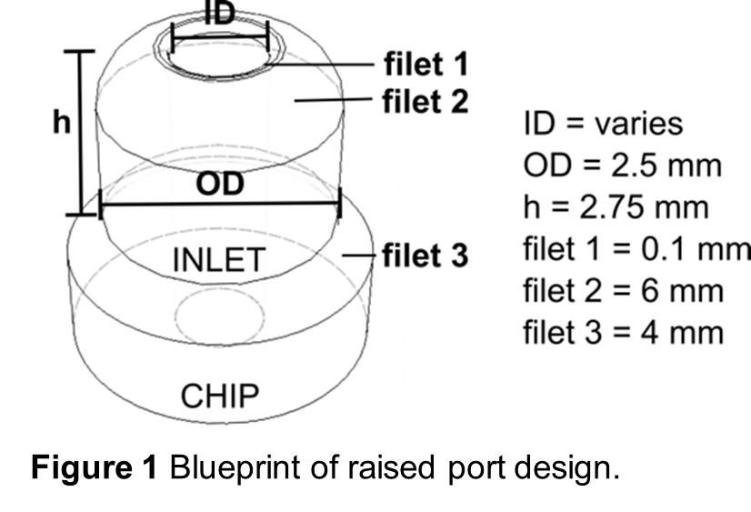
 - Above each port location, create a cylinder 2.75 mm tall with a 2.5 mm outer diameter ( 1). These are the standard dimensions that will fit with the optional ferrule locks in later steps.
- A hole in the center of the cylinder should be created to reach from the top of the cylinder down to the channel or port of the chip (“ID”, 1). The diameter of this hole should be customized to best fit the outer diameter of the tubing being used. (See next section for tips.)
- Filets should be added at three key locations ( 1).
- Filet 1 is at the edge of the inner cylinder hole and is set to 0.1 mm.
- Filet 2 is at the top, outer edge of the cylinder and is set to 6 mm.
- Filet 3 is at the base of the cylinder where the port meets the chip and is set to 4 mm.
- Once the raised port designs are added to the chip, use your printing software to
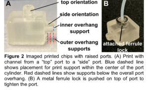 orient and build supports for the print as needed ( 2A)
- Ports located on the “top” face of the chip (facing away from the baseplate during printing) do not require supports.
- Ports located on the “side” faces of the print do typically require at least one support for both the inner diameter and outer diameter overhangs
- Once printed and post-processed, tubing should fit directly into the ports, with close, conformal contact.
- Optionally, for further connection support, a ferrule lock can be used:
- Start by sliding the ferrule lock over the tubing before inserting the tubing into the raised port.
- Once inserted, slide the ferrule lock over the raised port ( 2B) to gently tighten the port around the tubing.

What else should I know?
The raised port designs were compared to a printed chip-to-syringe female thread luer inlet and a simple printed hole in the chip, and tested by driving flow through a simple microfluidic channel. We tested printability, ability to maintain a seal during multi-day fluid flow, and ability to be re-used without wearing down in two different resins (MiiCraft BV007a and FormLabs Clear). We also attempted to print the design using a fused deposition modeling (FDM) printer.
For printability, the raised port and simple hole designs printed successfully more often in resin printed chips than did luer lock ports, likely due to size and lack of threading.
For reuse, we found that the raised ports typically retained a good seal with the tubing through > 20 rounds of inserting, removing, and re-inserting tubing, in both FormLabs and MiiCraft resins. Use of the ferrule lock enabled additional re-use of resin printed raised ports. In comparison, simple embedded holes wore down ~7x reuse on average. This is likely due to faster wear around the edges from mechanical stress, from repeated use in addition to forces from material shrinkage that act on the hole by the surrounding printed shape.8
For durability of the connection, prolonged use of the ports was tested over one week by continually pumping saline solution through single-channel chips at 37°C at a rate of 1 µl min-1. It was found that the quality of the seal was primarily limited by resin stability under these conditions, rather than by mechanical wear at the port. Chips printed with BV007a resin began to leak and deform at both the port site and other channel locations after 48 hours, whereas chips with FormLabs Clear resin were stable for at least 5 to 7 days without any noticeable signs of leaking or wear at the ports. These results are consistent with our prior findings that BV007a prints are sensitive to extended heat treatment.8 We conclude that the port design is likely to yield a durable seal as long as the material is stable under the conditions of the experiment.
For additional stability, ferrule locks can also be added to further support and increase the duration of tubing-to-chip connections, especially for devices experiencing challenges with backpressure.
This design for ports works best with resin/vat-polymerization printers that have high print resolution (i.e. are able to print features around 1 mm in scale or lower) and with materials that are stiff yet slightly pliable, such as the listed resins. This design could in principle be adapted for high resolution fused deposition (FDM) printing but would again fair better with slightly pliable materials; we found that more rigid plastics such as polylactic acid (PLA) were difficult to combine with soft tubing, especially if FDM print tolerance is inconsistent.
Several design files are included for convenience on our dataverse website (https://dataverse.lib.virginia.edu/dataverse/PompanoLab). These files can be used “as is” to test fit with the tubing of interest or can be edited and added to an existing chip design.
Conclusion
The inlet design demonstrated in this work was found to be durable, versatile, and simple to fabricate for microfluidic chips printed with resin 3D printers. Though other systems work well for larger chips, the design shown here can be used when a smaller inlet connection is needed.
Acknowledgements
Research reported in this publication was supported by the National Institute of Allergy and Infectious Diseases under Award No. R01AI131723 and from the National Institute of Biomedical Imaging and Bioengineering under Award No. R03EB028043 through the National Institute of Health (NIH). The content is solely the responsibility of the authors and does not necessarily represent the official views of the National Institutes of Health.
References
- Price, A. J. N., Capel, A. J., Lee, R. J., Pradel, P. & Christie, S. D. R. An open source toolkit for 3D printed fluidics. J. Flow Chem. 11, 37–51 (2021).
- van den Driesche, S., Lucklum, F., Bunge, F. & Vellekoop, M. 3D Printing Solutions for Microfluidic Chip-To-World Connections. Micromachines 9, 71 (2018).
- Au, A. K., Huynh, W., Horowitz, L. F. & Folch, A. 3D-Printed Microfluidics. Angew. Chem. Int. Ed. 55, 3862–3881 (2016).
- Anderson, K. B., Lockwood, S. Y., Martin, R. S. & Spence, D. M. A 3D Printed Fluidic Device that Enables Integrated Features. Anal. Chem. 85, 5622–5626 (2013).
- Weisgrab, G., Ovsianikov, A. & Costa, P. F. Functional 3D Printing for Microfluidic Chips. Adv. Mater. Technol. 4, 1900275 (2019).
- Bhargava, K. C., Thompson, B. & Malmstadt, N. Discrete elements for 3D microfluidics. Proc. Natl. Acad. Sci. 111, 15013–15018 (2014).
- Ji, Q. et al. A Modular Microfluidic Device via Multimaterial 3D Printing for Emulsion Generation. Sci. Rep. 8, 4791 (2018).
- Musgrove, Hannah. B., Catterton, Megan. A. & Pompano, Rebecca. R. Applied tutorial for the design and fabrication of biomicrofluidic devices by resin 3D printing. Anal. Chim. Acta 1209, 339842 (2022).


")