Imre Banlaki, Horst Henseling, Henrike Niederholtmeyer
Max Planck Institute for Terrestrial Microbiology, Marburg
Why is this useful?
As microfluidic chips increase in complexity, more and more tubes need to be connected to a chip for operation. That is especially the case where many pneumatic valves (“Quake valves”) are included in the design of two-layer devices [1,2]. In many cases, these valves are actuated by a central, electronic switch board, driving solenoid valves [3]. The central switchboard makes each individual valve easily programmable for multiple applications.
The drawback of this versatile set up is the need to rewire all connectors to a new chip to initiate the experiment. This is time consuming and increases the likelihood of human error, especially if the setup is used by multiple researchers, who use different chips.
A plug and play solution would allow each researcher to have their personal end pieces connected to their chips and interfacing with the switchboard. This allows preparation on the lab bench and facilitates the change from one experiment to another.
To that end, we designed a 3D printable mould to cast PDMS trapezoids with 8 integrated tubes (Fig. 1). The shape and tube-pattern make the connector unambiguous, similar to a VGA or D-sub electronics connector. A D-sub microfluidic connector of similar design has been published before, however it relies on actual, disassembled D-sub connectors which have gone out of fashion [4].
What do I need?
PDMS Sylgard, Dow Corning
Resin 3D printer or other means of fabrication
Tygon tubing (0.51 x 1.52 mm) or other as preferred
Blunt dispensing needles 23G (0.43 x 0.64 mm)
Scissors
Pliers
Glass petri dish
4x M3x20 screws and nuts
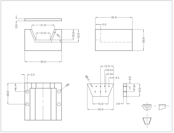
Figure 1 Blueprint of the pieces to fabricate and assemble the mould. Measurements in mm.
How do I do it?
- Fabricate the mould
3D print or mill the mould from a thermally stable resin, polymer or noncorrosive metal. We have shared our design on Metafluidics.org. (https://metafluidics.org/devices/vga-inspired-tubing-connector/)
Drill the holes in the trapezoid plate. Make sure the hole-array is axisymmetric by measuring each placement from the middle.
- Prepare the mould
Remove 8 metal pins from the plastic of the blunt dispensing needle tips. Cut 8 approx. 3-5cm Tygon tubing pieces and push them onto the end of the metal pins that was inserted in the plastic.
Insert the pins + tubing into the holes of the trapezoid plate (Fig. 2A).
Place the plate into the notch of the mould with the pins sticking out towards the shorter end, and screw the top plate on (Fig. 2C+D).
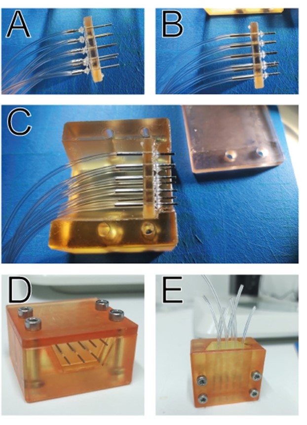
Figure 2 Assembly steps of the mould. A) Pins and tubing inserted in the trapezoid plate to fabricate a plug. B) Pins and tubing inserted in the plate to fabricate a socket. C) Plate, with pins and tubing, placed into the grove before adding the top plate. D) Fully assembled mould with flush pins sticking out. E) Vertical placement of assembled mould ready to be filled.
- Cast the PDMS
Mix 10g PDMS resin (1:10 as per supplier instruction).
Place the mould vertically so the hole is on top (Fig. 2E). Make sure the pins are flush with the bottom (use the petri dish). Arrange the bend of the tubing in a way that makes it easy to identify which tube belongs to which pin.
Cast the PDMS until at least 50% of the mould is filled.
Cure in the oven at 80°C for 30-60 mins.
- Remove the connector
After curing, unscrew and remove the top plate. Carefully remove the PDMS piece including the trapezoid plate from the mould. Now, you should be able to slide the plate off the pins.
The tubing on the back end is now ready to be connected to tubing from a control board by individual bridging with metal pins. The front end forms the quick connector for 8 lines.
- Setup for receiver socket
To cast a receiver socket, insert 8 metal pins without tubing into the trapezoid plate. Now connect some tubing to the pins so that the plate is sandwiched between pin and tubing (Fig. 2B). Insert the assembly into the mould as before and cast the PDMS. After curing and removal of the piece, the metal pins can be pulled out leaving only the tubing embedded within the PDMS.
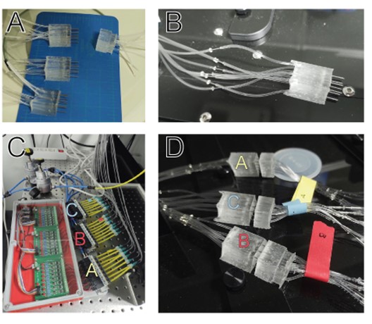
Figure 3 Plugs and socket A) after removal from the mould and B) connected to the switch board. C) Switch board with 24 valves clustered into 3×8 (A, B, C) control lines. D) Three plugs (A, B, C) connected to sockets.
What else should I know?
Curing without degassing may create bubbles, and depending on the resin for 3D printing the surface may remain somewhat sticky. This will not affect functionality. The stickiness can be avoided by placing the mould in isopropanol for a few days. Adding pigment to the PDMS could be used to colour code each plug. Expanding the design for more lines should be possible but connecting will be increasingly difficult.
Uncareful connection, puncturing the PDMS, may clog a pin.
When milling the device, instead of 3D printing, it is advised to change the plate shape and notch to a semi-circle and mill on the face to guarantee a flush fit of the plate.
Acknowledgements
This work was supported by Deutsche Forschungsgemeinschaft grant NI 2040/1-1.
References
- Unger MA, Chou H-P, Thorsen T, Scherer A, Quake SR. Monolithic Microfabricated Valves and Pumps by Multilayer Soft Lithography. Science. 2000;288: 113–116. doi:10.1126/science.288.5463.113
- Niederholtmeyer H, Stepanova V, Maerkl SJ. Implementation of cell-free biological networks at steady state. Proc Natl Acad Sci. 2013;110: 15985–15990. doi:10.1073/pnas.1311166110
- Brower K, Puccinelli RR, Markin CJ, Shimko TC, Longwell SA, Cruz B, et al. An open-source, programmable pneumatic setup for operation and automated control of single- and multi-layer microfluidic devices. HardwareX. 2018;3: 117–134. doi:10.1016/j.ohx.2017.10.001
- Scott A, Au AK, Vinckenbosch E, Folch A. A microfluidic D-subminiature connector. Lab Chip. 2013;13: 2036–2039. doi:10.1039/C3LC50201E


")