Richard J. Holmes and Nicholas J. Goddard
School of Chemical Engineering and Analytical Science (SCEAS),The University of Manchester, Manchester, UK
Why is this useful?
We demonstrate the use of double-sided adhesive films in the development of rapid prototype flow systems. These prototype fluidic devices have a great number of applications and since their preparation is a trivial matter, they may be prepared as and when required. Where there is a requirement for fluidic systems with a greater depth than the thickness of the film, multiple layers may be employed to expand the range of device depths obtainable.
What do I need?
- ARCare 8725 double-sided adhesive (or similar)
- Craft Knife, cutting board, template/ruler, etc.
- Polycarbonate (or glass) slides with appropriately located inlet and outlet holes.
What do I do?
1. First, prepare the substrate and superstrate, cleaning both and locating any inlet and outlet connectors and / or holes as appropriate.
2. Prepare a template of the channel design required and transfer this to the backing tape of the adhesive film.
3. Cut the adhesive film using the sharp craft knife, removing all traces of the template drawing, thereby leaving a double-sided adhesive film with missing segments corresponding to the desired flow system.
4. Adhere the film to the underside of the superstrate ensuring access to the inlet and outlet wells.
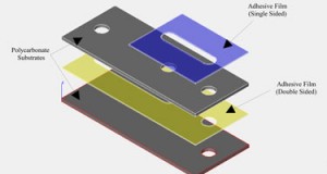
5. Remove the backing tape and attach the substrate slide, applying pressure to the system to assist adhesion process, creating a sandwich structure where the adhesive film defines the microfluidic system.
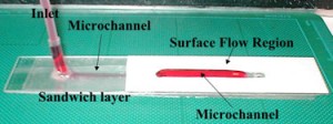
The device shown in the Figures 1 and 2 combines an internal flow system with an external flow system, using multiple layers of the adhesive tape to define a flow profile on the upper surface of the chip, whilst maintaining fluid confinement.
Figure 3 shows a cross-section of the device. This system may also be utilised for the formation of devices where the channel is pre-defined in either the substrate or the superstrate, as shown in Figure 4.
Figure 5 shows a cross-section of the device.
What else should I know?
The method presented above is a useful technique in the preparation of flow systems for microfluidics work on a prototype scale. Whilst the limitations of the system are obvious in so far as pressure driven systems, where high pressure flow will result in rupture of the device, and the use of a silicon-based adhesive limits the applications for any systems requiring abrasive chemical or surface chemistry, it does provide ample opportunity to demonstrate a flow system, producing a working model in a very short space of time.


