Daniel Olivero and Z. Hugh Fan
Department of Mechanical and Aerospace Engineering, University of Florida, Gainesville FL, USA
Why is this useful?
Bonding is a critical step in fabricating plastic microfluidic devices.[1] It is a process to seal microfeatures (e.g. channels) in a plastic substrate with a cover film. Lamination is one of the best methods to achieve a successful bond, with no air bubbles between the plastic substrate and film, no distortion of microfeatures, and minimum deformation of the device.[2] The parameters affecting the quality of lamination include the heating temperature, the pressure placed on the assembly, and the lamination process.[2] This tip describes using a commercially available, tabletop, roller laminator to seal a plastic substrate with a cover film. The plastic substrate (1.5 mm thick) is made from a cyclic olefin copolymer (COC) resins (Zeonor® 1020) and the film is a 100 µm thick COC film (Topas® 8007).
What do I need?
- A plastic substrate with microchannels (1″ x 3″)
- A thin film (1″ x 3″)
- Metalized Mylar films
- A hot plate
- A conventional laminator (GBC® Catena 35, Lincolnshire, IL)
The set up
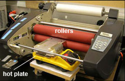
To preheat the plastic substrate to a temperature close to the lamination temperature, the laminator is modified as follows. The feed table in front of the rollers is removed and replaced with a hot plate as shown in Figure 1. The hot plate is raised to align the plate surface with the gap between the two rollers. The hot plate is used to preheat the plastic substrate so that it is easier to reach the required temperature for lamination of COC devices.
What do I do?
1. Clean both the plastic substrate and the cover film in purified water in an ultrasonic bath. Then rinse them in acetone and dry them in a clean air in a laminar hood. Make sure that both the substrate and the film are completely dry before proceeding.
2. Assemble the plastic substrate with the cover film. In our case, alignment is not required since all features are in the substrate. If any feature is made in the cover film, accurate alignment is likely needed.
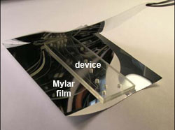
3. Cut two pieces of Mylar sheets sufficiently large to cover both the plastic substrate and the cover film. Place them between two Mylar sheets as shown in Figure 2. The Mylar sheets are used to prevent the texture of the rollers from being transferred to the plastic device, maintaining a smooth surface of both substrate and film.
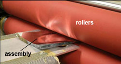
4. Place the assembly of the plastic substrate, the cover film and the Mylar sheets on the hot plate. Make sure that the cover film is at the bottom side, so that the heat is easier to be transferred to the interface between the film and substrate. Place a microscope slide and weights (2 x 44 g) on top of the assembly to ensure the assembly is in contact with the hot plate, as shown in Figure 3. The slide allows a uniform pressure placed on the assembly. For the specific plastic substrate and film, the hot plate is set at a temperature of 73ºC. Other plastic materials likely require different temperatures as discussed in the literature.[2,3] Allow the assembly to be heated for four minutes.
5. After the completion of the pre-heating, remove the weights and the slide from the assembly. The laminator rollers should have been heated to a temperature of 124ºC. The gap between the rollers is set at 3 mm and the roller speed is set at 3 feet/minute. Press the “run” button of the laminator and gently slide the assembly into the rollers. Make sure that the plastic substrate and the film do not become misaligned while sliding. Once the assembly enters the rollers it should move by itself through the laminator as shown in Figure 4. If needed, the device may be rolled through the laminator once more to ensure a complete lamination.
6. Once completed a functional microfluidic device is obtained, as shown in Figure 5. This device was used for two-dimensional protein separation by integrating isoelectric focusing (IEF) and polyacrylamide gel electrophoresis (PAGE).[4] The device was filled with a dye for easy visualization of channels. Note that this lamination method can be used for other types of materials but the variables such as the lamination temperature likely need to be adjusted for a perfect lamination.
Acknowledgements
This work is supported in part by the grants (48461-LS and 52924-LS-II) from the USA Army Research Office and the startup fund from the University of Florida.
References
[1] L. J. Kricka, P. Fortina, N. J. Panaro, P. Wilding, G. Alonso-Amigo and H. Becker, Lab Chip, 2002, 2, 1-4.
[2] C. K. Fredrickson, Z. Xia, C. Das, R. Ferguson, F. T. Tavares and Z. H. Fan, J. Microelectromech. Syst., 2006, 15, 1060-1068.
[3] M. L. Hupert, W. J. Guy, S. D. Llopis, H. Shadpour, S. Rani, D. E. Nikitopoulos, S. A. Soper, Microfluid. Nanofluid., 2007, 3, 1-11.
[4] C. Das, J. Zhang, N. D. Denslow, and Z. H. Fan, ZH. Lab Chip, 2007, 7, 1806-1812.


