Jesse Greener, Wei Li, Dan Voicu and Eugenia Kumacheva
Department of Chemistry, University of Toronto, 80 St. George Street, Toronto, Ontario, Canada
Why is this useful?
Typical fluidic connections to PDMS chips consist of tubing inserted into a punched inlet, held in place by glue, for example, a cured epoxy glue. These connections can fail at low pressures because of weak adhesion of the glue to PDMS. In addition, insertion of the tubing directly into the inlet may affect the flow if the tubing is pushed right to the bottom of the channel, thereby increasing hydrodynamic resistance. This is particularly a problem for microchips made from a thin layer of PDMS. Furthermore, even subtle changes to hydrodynamic resistance at the inlet can affect flow rates from pressure-driven sources or cause differential flow rates through inlets which are supplied from a manifold that is being driven from a single source.
Upchurch has devised a low fluidic resistance chip connection system made from the polymer PEEK called a NanoPort, which can easily accommodate new feeds via a threaded nut and ferrule system.[1] However, this device is designed as a single-use port which is sealed to the chip via a permanent bond at its base using an adhesive ring. The adhesive ring does not stick well to untreated PDMS but plasma treatment of the fully cured PDMS surface has been reported to enhance the bond between the NanoPort/adhesive ring assembly and PDMS.[2] This technique has the advantage of being able to handle working pressures of between 30-50 PSI, but suffers from the single use nature of the adhesive ring. For connections to PDMS chips, Upchurch recommends that the NanoPort be imbedded in the PDMS during microchip curing. This technique is not ideal because the sealing surface area is relegated to the bottom of the NanoPort only, and the semi-cured state of the PDMS is not conducive to creating a strong bond. Other groups have fabricated their own, low cost PDMS connectors, which may be a convenient substitute for the NanoPort in low pressure applications.[3]
This tip reviews an alternative approach; encasing the NanoPort in PDMS at the surface of a previously cured PDMS microchip. Benefits include NanoPort reusability (after liberating them from the PDMS encasing) and higher useable pressure ranges (we determined that up to 85 PSI can be achieved). This technique can be easily adapted to chips of any materials which make a strong bond with PDMS, including glass and polycarbonate.
What do I need?
- PDMS SYLGARD 184 silicone elastomer base & curing agent (Dow Corning)
- Upchurch NanoPort assembly
- Plasma cleaning system for PDMS surface oxidation
- A heat source (convection oven)
- One 3 cm-long piece of tubing with 1.59 mm OD (1/16 inch) per inlet
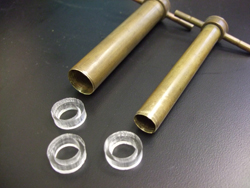
- Knife or 2 differently sized cork borers, the smallest of which should be at least 1.0 cm (we used 1.7 and 1.0 cm diameter)
What do I do?
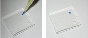
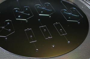
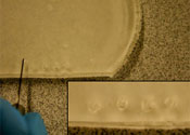
1. Prepare the PDMS chip, ensuring that access holes with diameter of roughly 1.5 mm are punched into the surface.
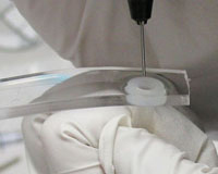
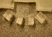
2. Punch or create PDMS rings with thickness no less than approximately 5 mm.
- Figure 1
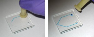
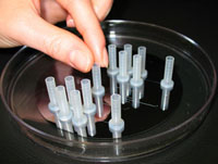
3. Insert 1/16 inch OD tubing into the inlet holes to block PDMS from entering the device.
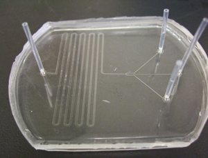
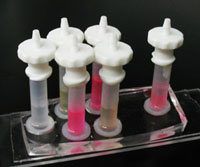
- Figure 2
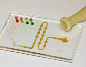
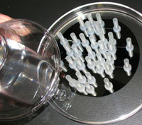
4. Plasma bond the PDMS rings centered around the inlet holes on the PDMS chip (we use 90 seconds at 600 mTorr). This serves as a reservoir for liquid PDMS for the following steps.
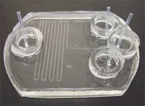
- Figure 3
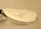
5. Coat the bottom of the reservoir with less than 1 mm of liquid PDMS, then place the NanoPort base over the tubing in the PDMS reservoir. Make sure at this stage that no air bubbles are trapped at the bottom of the NanoPort in the groove designed for the o-ring, which we are not using for this application. This can be accomplished by rotating the port’s base in the liquid PDMS within the reservoir while sliding it up and down slightly around the tubing to allow air to escape. Degassing under vacuum may also work.
6. Finish filling the reservoir with PDMS, being careful not to get any in the threaded area of the NanoPort or inside the tubing, and heat cure (we used 4 hours at 74ºC).
7. After curing, pull the tubing out of the inlet. If any PDMS leaked into the threaded part of the NanoPort base this can be removed with tweezers or by repeatedly connecting and disconnecting the base’s male threaded counterpart (nut). Clear debris with compressed air.
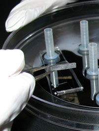
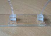
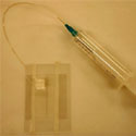
8. Connect the nut and ferrule (or coned nut) to 1/16 OD tubing, attach to the NanoPort base and supply liquid or gas to the chip.
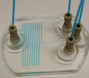
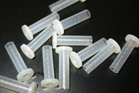
- Figure 4
What else should I know?
In this example, we apply this technique to mounting NanoPorts on to a PDMS microchip. In theory, other substrates can benefit from this technique as long as they can be bound to PDMS either by plasma treatment, or by curing liquid PDMS to it. Also, the PDMS ring provides a leak-proof reservoir for liquid PDMS which results in a clean finish when affixed to the surface via plasma treatment. However, rings can also be stuck to the surface via curing a thin coat of liquid PDMS between the two, though the finish may not look as nice.
Our pressure tests probed the strength of the bond between the NanoPort and PDMS. Therefore a flat piece of PDMS substrate was used instead of a microchip with channel structures. By progressively increasing the pressure of an inert gas (N2) being supplied to the NanoPort assembly it was determined that in every case the failure occurred between its base and the top of PDMS substrate. In our tests, failure occurred between 40 and 85 PSI. In theory, the assembly would benefit from more contact area between the PDMS/NanoPort assembly and the PDMS chip. A wider PDMS reservoir would accomplish this, though inlet spacing would have to be adjusted to account for the larger assembly footprint over each inlet. In addition, changing the ratio of silicone elastomer to curing agent and/or implementing this technique on a surface that has not yet fully cured or has been freshly plasma treated may also help to strengthen this bond. The same NanoPorts used in previous tests were then attached to a working microfluidic chip and subjected to increasing gas pressure. In this case, the chip itself separated before the reusable NanoPort connection failed.
References
[1] http://www.upchurch.com/PDF/I-Cards/N4.PDF
[2] C. Koch, J. Ingle, and V. Remcho, Bonding Upchurch® NanoPorts to PDMS, Chips & Tips (Lab on a Chip), 12 February 2008.
[3] S. Mohanty, D. J. Beebe and G. Mensing, PDMS connectors for macro to microfluidic interfacing, Chips & Tips (Lab on a Chip), 23 October 2006.


