Author Archive

Rapid curing of PDMS for microfluidic applications

Adrian O’Neill, Jeffrey Soo Hoo and Glenn Walker
Joint Department of Biomedical Engineering, University of North Carolina-Chapel Hill and North Carolina State University

Why is this useful?


A new curing procedure is presented to expedite poly(dimethylsiloxane) (PDMS) microfluidic device fabrication. For microfluidic applications, PDMS is typically cured over a master in a plastic Petri dish at 80ºC for 2.5 hours. The curing temperature is limited by the maximum temperature a plastic Petri dish can withstand without warping. Dow Corning Sylgard 184 PDMS can be cured over a range of times and temperatures, spanning ~48 hours at room temperature to 10 minutes at 150ºC.  We present an alternate curing method, using an aluminium foil dish, that reduces the curing time from 2.5 hours to 10 minutes.

What do I need?


  • Aluminium foil, 0.001 inch thickness or greater
  • 90mm diameter crystallization dish (Pyrex 90 x 50mm)
  • PDMS (Dow Corning Sylgard 184)
  • Hotplate (Barnstead 721A digital hotplate)

What do I do?


1. Cut a 4.5 inch diameter circle out of aluminium foil, being careful not to wrinkle the foil. Wrinkles may tilt the master causing the thickness of the PDMS mould to vary from one side of the design to the other.

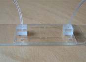
Figure 1.

2. Form the foil over the bottom of the 90mm crystallization dish, as shown in Figure 1.

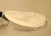
Figure 2.

3. After gently removing the foil, place the master in the foil dish and put the dish on a room temperature hotplate.

4. Mix the PDMS according to the manufacturer’s procedure [1].

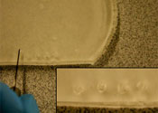
Figure 3.

5. Pour the desired amount of PDMS over the master, as shown in Figure 2.

6. Set the hotplate temperature to 150ºC. Once at 150ºC, cure the PDMS for 10 minutes.

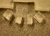
Figure 4.

7. Remove the foil dish from the hotplate and allow it to cool to room temperature.

8. Gently peel or cut the aluminium foil from the master and cut away any excess PDMS (Figure 3).

9. Finally, peel the PDMS mould from the master (Figure 4).

References


[1] Dow Corning Product Information, “Information about Dow Corning® brand Silicone Encapsulants,” 2005.

Digg This
Reddit This
Stumble Now!
Share on Facebook
Bookmark this on Delicious
Share on LinkedIn
Bookmark this on Technorati
Post on Twitter
Google Buzz (aka. Google Reader)

PDMS connectors for macro to microfluidic interfacing

Swomitra Mohanty, David J. Beebe
University of Wisconsin Department Biomedical Engineering
Glennys Mensing
University of Illinois Department of Mechanical & Industrial Engineering

Why is this useful?


The purpose of this Tip is to show a simple method to connect the microfluidic world to the macro world.  Microfluidic devices are constructed from a variety of materials including glass, silicon, and polymers.

No matter how microfluidic devices are constructed, one common problem has been employing a user friendly method to connect standard fluidic equipment such as syringes, to the microfluidic device.  Often researchers attempt to use commercially available micro-tube fittings by gluing them to ports on a microfluidic device.  These fittings are small in size and difficult to work with and the glue can clog the port.  To solve this problem we employ an in house fabricated PDMS connector that consists of a hole through the center and uses double-sided adhesive to connect to the microfluidic device.

What do I need?


  • PDMS SYLGARD 184 silicone elastomer base & curing agent (Dow Corning)
  • 3″ Petri dish
  • One utility knife (McMaster Carr Supply Company No.:35575A71)
  • Grace Bio-Labs Secure-Seal Adhesive (double sided) (SA-S-1L)
  • Whatman 42 filter paper (9 cm Whatman No.:1442-09 )

The purpose of the filter paper is to help bond the PDMS to the double sided adhesive.  However the pores in the filter must be large enough for PDMS to penetrate.  Pore sizes between 2 -8 µm are appropriate

  • One blunt 16 gauge reusable steel needle (Integrated Dispensing Solutions Part # 9991279-2)

The blunt needles are used to core through the PDMS.  Care needs to be taken when coring otherwise tears may occur in the hole causing the PDMS connector to leak.  The inside of the blunt needle can be sharpened  using a round file.  Simply insert the file into the tip of the needle and file the inner edge till it is sharp.  This will make a cleaner hole through the PDMS.

The size of the needle will depend on the tubing size you are using to connect to your device.  Choose a needle size that is slightly smaller than the tubing you are using.  The PDMS will flex around the tubing and provide a good seal.

What do I do?


1. Trace Petri dish on adhesive and cut out circle  Typically 6 Petri dishes can be traced on a single Grace-Biolabs sheet.  The template provided can be used to help cut out circles.

2. Peel off the paper side of the adhesive and place the sticky side onto the filter paper. Apply pressure over the entire area to remove any air bubbles

Figure 1.

3. Place the filter/adhesive into the lid of the Petri dish.  Make sure the filter paper faces up and that the whole filter/adhesive assembly lies flat against the dish. Do not worry if the edge of the filter/adhesive curls up a little on the side. This will result in thinner PDMS connectors on that side.
Adhesive cicle in petri dish plus uncured PDMS


Figure 2.

They will still be functional. Mix 25 g of PDMS with 2.5 g (10%) hardening agent and pour it into the dish (Figure 2).  Place on a hot plate at 50 degrees Celsius and cure for 4 h.

4. Remove the dish from the hot plate and let cool for 5 min.  Using the knife cut the PDMS around the edges of the dish to loosen it.  Then pry the PDMS from the dish (Figure 3).


Figure 3.

5. Take the 16 gauge blunt needle and place it on the surface of the PDMS.  Turn the needle back and forth while applying pressure to create a through-hole.  Make several holes in a row (Figure 4).


Figure 4.

6. Take the knife and cut squares around each of the holes.  After cutting out the row, each hole can then be separated into individual connectors (Figure 5).

Figure 5.

7. Clean the surface of your microfluidic device with some ethanol.  (The surface must be clean for good adhesion.)  Peel the adhesive off the bottom of the PDMS connector. This should remove the PDMS core made with the blunt needle. If not, you may need to remove it with fine tweezers.

8. Attach the connector to your microfluidic device.  Insert tubing into the connector and attach the other end to a fluidic source such as a syringe (Figure 6).

Figure 6.

Digg This
Reddit This
Stumble Now!
Share on Facebook
Bookmark this on Delicious
Share on LinkedIn
Bookmark this on Technorati
Post on Twitter
Google Buzz (aka. Google Reader)

Avoiding bubble injection by droplet merging

Edmond W.K. Young, Aaron R. Wheeler and Craig A. Simmons.
University of Toronto, Canada.

Why is this useful?


In many microfluidics applications, the presence of bubbles can be undesirable because of their tendency to disturb fluid flow in microchannels.  For cell culture studies in particular, cells that are not strongly adhered to the underlying substrate can be sheared, detached, and entrained by passing bubbles, leaving behind regions depleted of cells.  Many microchannel designs therefore incorporate either bubble traps [1] or complex valve configurations [2] to eliminate bubbles from being introduced into the channels.  However, these elements add complexity, and thus are not ideal for use with rapid prototyping experiments, in which fluid is typically delivered by means of a syringe. We present a tip that avoids the common phenomenon of bubble injection by careful attention to reservoir fluid volumes.

What do I need?


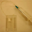
  • PDMS-glass microchannel, irreversibly sealed, with polyethylene tubing (Intramedic) inserted into cored-out holes in the PDMS and sealed with epoxy (LePage)
  • Syringe, 1 mL (BD)
  • Syringe needle, 18 gauge (BD)
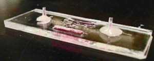
  • Fluid mediumTypical Microfluidic Chip

Figure 1. A Typical Microfluidic Chip

What do I do?


Prior to sample injection, the microfluidic device is primed with fluid and the inlet and outlet ports are not completely filled (Figure 1).  If a syringe needle is inserted into the inlet port (Figure 2a) at this stage, air will be trapped between the syringe needle and the liquid-air interface, causing bubbles to be injected into the microchannel. To avoid this phenomenon:

1. Insert syringe needle into outlet port (Figure 2b).  Note that this traps a bubble on the outlet side.

2. Slowly depress syringe to push fluid toward the inlet side.  Do so until fluid reaches the top of the inlet port and forms a small bead.
3. Remove syringe needle from outlet port.  Note that the liquid interface on the outlet side should now be lower than before Step 2.  However, the trapped bubble from Step 1 should now be eliminated.

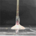
4. Depress syringe to generate a small droplet at the tip of the needle (Figure 2c).

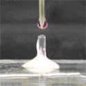
5. Touch the droplet at the needle tip to the bead of fluid at the inlet (Figure 2d).  Merging the droplet and the bead prevents formation of an air bubble.
6. Inject sample from syringe into channel as desired; no bubbles will be injected.

Figure 2a

Figure 2b

Figure 2c

Figure 2d

References


[1] E. Leclerc, Y. Sakai, and T. Fujii, Cell culture in 3-dimensional microfluidic structure of PDMS (polydimethylsiloxane). Biomed. Microdevices, 2003, 5(2), 109-114.
[2] L. Kim, M.D. Vahey, H.-Y. Lee, and J. Voldman, Microfluidic arrays for logarithmically perfused embryonic stem cell culture. Lab Chip, 2006, 6, 394-406

Digg This
Reddit This
Stumble Now!
Share on Facebook
Bookmark this on Delicious
Share on LinkedIn
Bookmark this on Technorati
Post on Twitter
Google Buzz (aka. Google Reader)

Vacuum filling of microfluidic devices

Ivar Meyvantsson and David J. Beebe
Department of Biomedical Engineering, University of Wisconsin – Madison, USA

Why is this useful?


Poly(dimethylsiloxane) (PDMS) is hydrophobic in its native state. When fluid is forced into a PDMS microfluidic channel using pressure, bubbles are often formed. One way to facilitate filling is to make the PDMS surface hydrophilic by exposing it to oxygen plasma. However, bubbles can still form despite surface hydrophilicity and the lifetime of plasma-induced hydrophilicity is limited to a few hours. An alternative method of filling microfluidic networks and arrays has been reported by Monahan et al.[1], which is more effective than hydrophilic surface treatment alone. We present a procedure based on that described by Monahan et al. and provide additional comments related to cell biology applications of PDMS devices.

What do I need?


  • Vacuum desiccator (e.g. Fisher scientific cat. no. 08-594-15A).
  • Vacuum pump (e.g. Gast DOA-P704-AA, capable of producing 84kPa vacuum).
  • Air filter (e.g  Millipore Aervent-50 Disposable Filters).
  • An open container (e.g. petri dish) for microfluidic device. Choose a container that, when filled to cover the bottom surface, can be tilted to expose at least half the bottom surface.

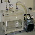
Vacuum dessicator and vacuum pump

Equipment required for vacuum filling of chip

What do I do?


1. Connect vacuum pump to vacuum desiccator outlet. If aseptic operation is required place air filter on desiccator inlet, spray inside of vacuum desiccator with 70 % ethanol (v/v in water) for sterilization, and wipe dry. Also, for aseptic operation, choose a container with a lid to enable transfer between biohood and desiccator.

2. Prepare a microfluidic device (e.g. PDMS part bonded to a glass slide), a container that holds the device (e.g. petri dish), and the solution you wish to fill the device with.

3. Place microfluidic device in the container.

4. Fill the container with fluid such that all microfluidic device access ports are covered. Place the submerged microfluidic device in the desiccator.

5. Turn the vacuum pump on, open the desiccator output valve, and close the input valve. Apply vacuum for 5-10 minutes. The bubbles that come out of the ports tend to cling to the rims of the ports.

6. Tilt the desiccator to expose the entire surface of the microfluidic device to air. This will “pop” all the bubbles. If tilting is insufficient, agitation (i.e., tapping, knocking, etc.) can also help remove bubbles.

3. Chip in Container

4. Submerge chip in fluid

Submerged chip after evacuation

6. Tilt dessicator to remove bubbles

7. Open the appropriate valve to bring the desiccator chamber back to atmospheric pressure. Visually inspect the channels to determine if they have been filled. Small bubbles (under 500 microns diameter) remaining at this point often disappear within 10 minutes if the device is left submerged in the fluid.

8. If bubbles persist, extending vacuum application or repeating steps 3 – 5 will improve filling.

9. This method works with a variety of fluids, including phosphate buffered saline (PBS), Dulbecco’s modified Eagle’s medium (DMEM) and protein-supplemented (e.g., bovine serum) DMEM, although proteins tend to modify the surface properties of PDMS making it more hydrophilic. The use of such fluids for initial filling is important when accurate concentrations are critical, such as in mammalian cell culture.

Final fluid filled chip

References


1. J. Monahan, A. A. Gewirth, and R. G. Nuzzo, A method for filling complex polymeric microfluidic devices and arrays, Anal. Chem., 2001, 73, 3193 – 3197.

Digg This
Reddit This
Stumble Now!
Share on Facebook
Bookmark this on Delicious
Share on LinkedIn
Bookmark this on Technorati
Post on Twitter
Google Buzz (aka. Google Reader)