Sukru U Senveli, Rajapaksha WRL Gajasinghe, and Onur Tigli
Department of Electrical and Computer Engineering, University of Miami, Coral Gables, FL, USA and
Biomedical Nanotechnology Institute at University of Miami (BioNIUM), Miami, FL, USA
Why is this useful?
PDMS (Polydimethylsiloxane) is a widely used material for fabricating microchannels through molding processes. In some studies, the exact position or dimensions of the PDMS microchannel on an active substrate is not very important, especially if no active manipulation or sensing is desired with microfluidics. However, there are many studies that can benefit from precise aligning of microchannels to structures on a substrate for optimum system performance. In such cases, coarse alignment using only tweezers may not be an option as overlay accuracy is limited to around millimeter scale. Plasma activated PDMS is a good example of this case where irreversible bonding requires bonding with one try in a short amount of time. Furthermore, there are cases in which the outer dimensions of the PDMS slab become important where cutting the PDMS using razors alone is not precise enough. Possible reasons for needing well-defined outlines include housing requirements and necessity of electrical access.
This study deals with methods to
- fabricate microchannels with well-defined shapes using a plastic template on a handle substrate and
- align and bond these microchannels onto an active substrate with high precision.
The error in outline dimensions of the microchannels was seen to be approximately 100 µm but it is ultimately limited by the 3D-printer’s accuracy. On the other hand, the overlay error was measured to be as small as <10 µm in our experiments.
We demonstrate the method on bonding of microchannels to surface acoustic wave devices on a lithium niobate substrate. The microchannel and the sidewalls need to be in the center of the region between the two devices facing each other whereas the electrical pads should be accessible and not covered with PDMS.
What do I need?
|
|
What do I do?
Microchannel Fabrication with 3D-Printed Template
1. It is assumed that SU-8 patterns are already formed on a silicon wafer as shown in Fig. 1(a). A template mask is designed with a CAD program and fabricated using a 3D-printer with ABS type plastic to define the outline of the microchannels. A template thickness of at least 3 mm is recommended for durable microchannels and less than 6 mm is recommended for ease of punching. Fig. 1(b) shows the template structure made of ABS.
2. Under a chemical fume hood, one drop of tri-chloro-silane is placed on a microscope slide, which is in turn placed in a small vacuum chamber. The silicon wafer with SU-8 microchannel patterns is placed inside alongside the microscope slide. The chamber is closed and pumped down. After pumping down for 5 minutes to -0.8 atm of relative vacuum, the chamber is left for 2 hours for silane deposition on the silicon surface. Silane formation is visually checked after the prescribed duration as shown in Fig. 1(a).
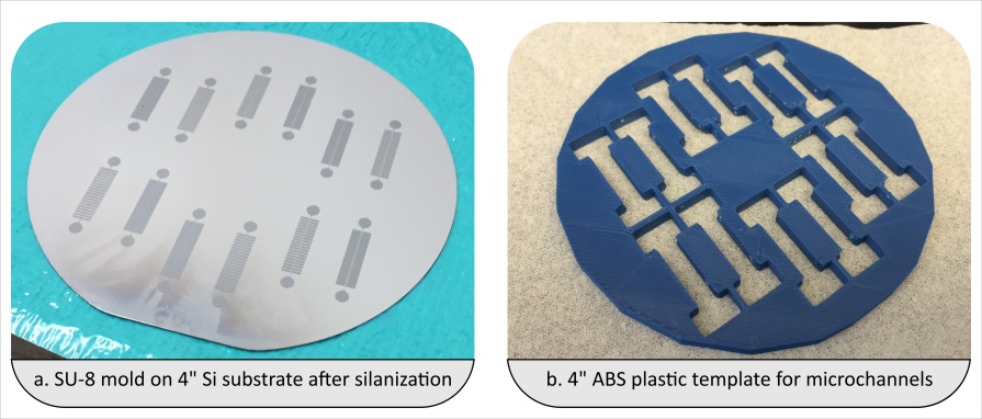
Fig. 1 (a) Silanized mold with SU-8 features of the microchannels. (b) The 3D-printed template for microchannel outlines.
3. The 3D-printed template is carefully aligned to the substrate and held in place using paperclips. PDMS (Sylgard) mixed at a ratio of 10:1 is poured onto the holes in the filter. The amount of PDMS leaking between the filter and the substrate should be kept to a minimum.
4. A razor or another flat and sharp object is used to sweep off the excess PDMS from the top. This makes it easier in the eventual alignment step using the microscope. The assembly with the plastic template in place on the substrate and filled with PDMS is shown in Fig. 2(a). Binder clips are used to hold them close together.
5. PDMS is left to cure overnight.
6. The template is separated from the substrate by first cutting through the interface with a razor from the sides and then wedging in with tweezers from four different locations around the substrate. A removed template is shown in Fig. 2(b).
7. Once the template is removed, the backsides of the microchannels are immediately covered entirely with Scotch tape to avoid any dust particles on the bonding surface.
8. Individual microchannels are popped out from the filter by applying uniform pressure from the top side.
9. Inlet and outlet holes are formed using biopsy punches with appropriate gauges. An example of individual channels obtained like this is shown in Fig. 2(c).
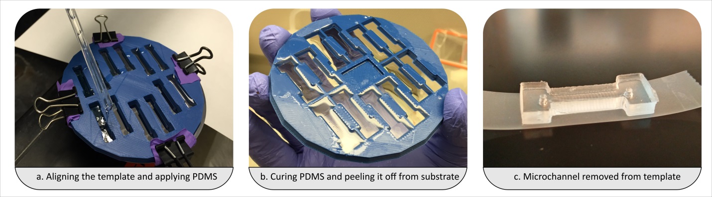
Fig. 2 (a) Template after aligning with the substrate is held in place using binder clips. (b) Template after separation from the substrate. (c) A microchannel popped out and punched for inlet and outlet.
Microchannel Alignment with 3D-Printed Alignment Apparatus on a Probe Station
1. The microchannels are placed in the alignment apparatus shown in Fig. 3(a) between the appropriate spring and the stationary beam which are displayed in Fig. 3(b). The choice of spring depends on the spring constant and the size of the microchannel. The microchannel should be sitting flat between the spring and the beam. This can be checked by looking from the side.
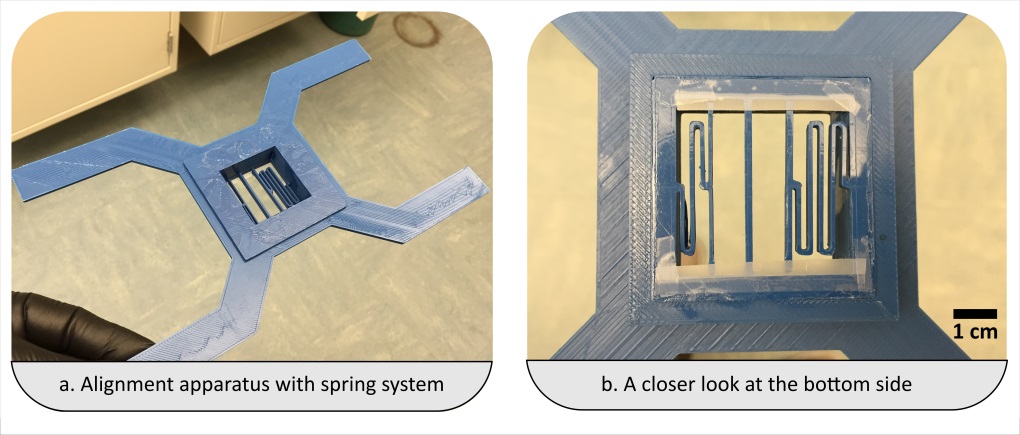
Fig. 3 (a) Alignment apparatus as prototyped. (b) Bottom side of the apparatus showing the stationary beam in the middle and two springs on either side for clamping the microchannel for alignment.
2. After correct placement of the microchannel, the scotch tape can be removed slowly by shearing it in order not to disturb the PDMS piece.
3. The alignment apparatus is slowly placed on the platen of the probe station. Neodymium magnets are placed on its four legs to balance and secure the alignment piece in place as shown in Fig. 4(a). A PDMS piece loaded against the spring with a lower spring constant and the stationary beam is shown in Fig. 4(b).
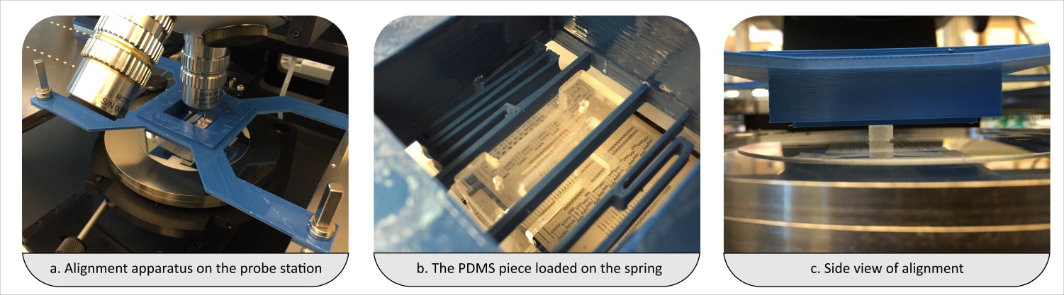
Fig. 4 (a) Alignment apparatus is secured using neodymium magnets on the probe station platen. (b) A closer look at a PDMS piece loaded onto the apparatus. (c) Side view of alignment.
4. Alignment is carried out while observing the overlay using the microscope of the probe station. The overlay is controlled by the stage which moves in plane with the substrate.
5. When the alignment is made, the microchannel is lowered carefully and slowly onto the substrate to bring them into contact as shown in Fig. 4(c).
6. Blunt tipped tweezers are used to apply pressure on the top of the PDMS piece to hold it in place and for a more uniform bond.
7. The spring is released with another set of tweezers. The alignment apparatus is raised by hoisting the platen without touching the sample again. The microchannel has been bonded at this step as displayed in Fig. 5 (a).
8. Microchannel alignment and bonding is double checked using the microscope as shown in Fig. 5(b-c).
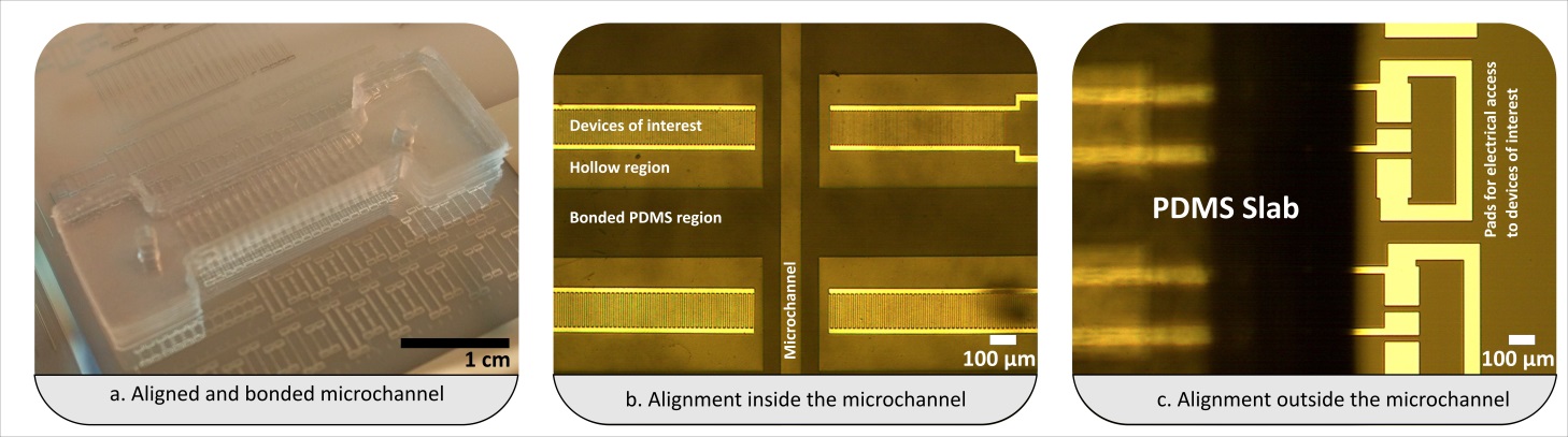
Fig. 5 (a) Photograph of after successfully completed alignment and bonding. (b) Evaluation of the alignment of the microchannel to a substrate containing a set of SAW devices. The PDMS is designed in such a way as to bond on areas excluding the interdigitated electrodes of the devices marked as “Devices of interest”. The microchannel was aligned down to an alignment error of <10 µm. (c) The PDMS slab outline does not cover the pads which are available for electrical access using probes.
What else should I know?
- Materials other than ABS might also be convenient for forming templates too but ABS was preferred due to its higher temperature resilience (in case a high temperature curing of PDMS is desired).
- If there is a considerable amount of leakage between the template and the handle substrate, it becomes harder to separate the two. This is where the silanization helps. Also, the microchannel outlines might need to be traced using a razor in case there is a substantial amount of residue.
- Overnight curing is optional. However, lower temperature/longer duration curing was seen to perform better than higher temperature/shorter duration curing step as it results in somewhat softer PDMS.
- The PDMS piece sitting flat on the alignment apparatus is of utmost importance. The bottom of a 4mm tall PDMS piece should be peeking about 2 mm from the bottom of the alignment apparatus.
- The Scotch tape can also be removed from PDMS before placement onto the apparatus but this can increase the chances of it collecting dust if not in a cleanroom environment.
- Activation of PDMS piece and/or substrate is optional. In our studies, we did not use an oxygen plasma and the microchannel was able to withstand microfluidic operations with estimated pressure levels about -200 kPa.
- Scotch tape was applied to the bottom side of the alignment apparatus to keep the springs from buckling down with the added mass from the PDMS piece.
Acknowledgment
Support from the National Science Foundation (NSF) under grant No. ECCS-1349245 is gratefully acknowledged by the authors.


")