Gurucharan V. Karnad*a,b, R. N. Ninad*b and V. Venkataraman a
a Dept. of Physics, Indian Institute of Science, Bangalore, India
b Dept. of Electronics and Communication Engineering, Amrita School of Engineering, Bangalore, India
* Corresponding authors: Gurucharan V. Karnad, R. N. Ninad
Email: gvkarnad[at]physics.iisc.ernet.in, rnninad[at]gmail.com
Why is this useful?
Spin coating is one of the coating techniques used to apply thin uniform films to flat substrates. A Spin Coater is a machine used for spin coating, and is one of the most ubiquitous instruments in any laboratory dealing with microfluidic devices.
Most commercial spin coaters are extremely expensive (≈ > US $1,995 [1]) and come with features and specifications not necessarily needed for fabricating and experimenting with polymer based microfluidic devices.
The cost of this instrument should not act as a deterrent for groups intending to venture into fabricating and experimenting with simple devices, hence the effort in this direction.
We have designed an inexpensive spin coater (with a touch-screen interface) costing less than US $350. The user input is through the touch-screen interface, where parameters such as spin duration and speed can be entered. Real time speed is also displayed alongside. A microcontroller forms the intelligence of the system and manages the inputs, display, and speed and duration control. The real time speed is sensed by the microcontroller using an optical encoder, and a control loop keeps it within acceptable error limits.
The substrate is mounted either using a double-side tape or a set of clamps. Improvements with regard to vacuum chuck, computer interfacing etc., can be done as per necessity.
What do I need?
- PIC Microcontroller Programmer (with support for 18F4550)
- PIC 18F4550 (≈ US $04.47 [2])
- Graphic LCD 128×64( JHD 12864E or equivalent) (≈ US $16.80 [3])
- TouchPanel (≈ US $07.00 [4])
- TouchPanel Connector Board (≈ US $04.00 [5])
- Infrared Distance Sensor (equivalent – Cytron IR01A Medium Range Infrared Sensor) – Optical Encoder-Sensor (≈ US $08.10 [6])
- Crystal oscillator circuit (11 Mhz Crystal Oscillator, 22pf Capactitor (2) – connection as given in PIC 18F4550 Datasheet) (≈ US $01.00 [7])
- IR 2110 (≈ US $07.25 [8])
- IRFP 150N (≈ US $02.77 [9])
- 1N 4744A (≈ US $00.21 [10])
- BYQ 28E200 (≈ US $00.98 [11])
- Brushed DC Motor (Como Drills 719RE850 or equivalent) (≈ UK £21.69 [12] ≈ US $35)
- Any PC CPU Case (for Power Supply-SMPS and as instrument control box) (≈ US $50.00 [13])
- PC (to program the microcontroller initially)
- Software – MPLAB IDE (Free), HI TECH C Compiler for PIC 18 MCU (Free Version)
- Machining, raw material, workshop access ( for chuck, optical encoder mount and motor cabinet) (≈ US $200.00)
What do I do?
- Interface and connect the PIC Microcontroller Programmer to the PC as per the instructions given in its manual
- Burn the Program01.hex file into the microcontroller with the help of the programmer
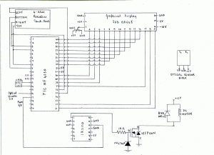
- Connect the microcontroller and other components as given in the circuit diagram (Figure 1). The circuit and display can be appropriately mounted in a PC CPU case
- Power up the circuit
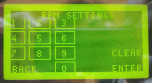
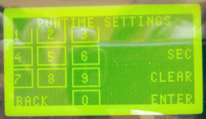
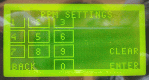
- The Graphic LCD should display data similar to Figure 2. Figure 3 and Figure 4 will appear on the display if appropriate icons on the Menu “Selected Values” screen are touched
- There can be dissimilarities with each touch panel and hence it may not respond to input due to change in touch co-ordinates. Hence, there would be a need to modify the Program01.c. If there are no problems, jump to instruction 11
- Install the software mentioned above
- Modify the program, by finding out the new co-ordinates of the icons by following the instructions given in readme.txt
- Compile the modified Program01.c and program the microcontroller as per the instructions given in the programmer manual
- Repeat instruction 2 to 5
- Make an appropriate box to mount the motor
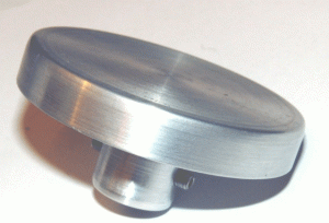
- An aluminium ( light and easy to clean) chuck (Figure 6, Figure 7) to fit the motor shaft has to be machined
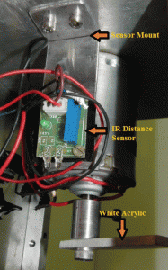
- A simple optical encoder set up which includes mounting of a slim white acrylic piece on the bottom of the motor shaft and the IR optical sensor has to be made ( Figure 5)
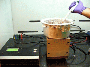
- Put together all the components appropriately. The spin coater (Figure 8 ) should now be ready ( appropriate modification of the chuck may result in a centrifuge too)
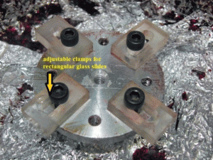
- Mount the wafer samples for spin coating either with a double-sided tape or a set of adjustable clamps
What else should I know?
- Basic knowledge of C is essential to modify the code to suit individual requirements or specification
- The spin coater has been set to receive input of speeds from 1000-7000 RPM ( limited only due the motor used, can be modified easily)
- The maximum spin time is 999 seconds (increments of 1)
- Due to nonlinear response of the brushed DC motors to voltage ( and hence varying PWM values), the speed response of the motor to variation in PWM values has to be plotted and an appropriate equation has to be estimated. The equation in Program01.C has to be modified (see the readme.txt). Note: This needs to be done only if a Brushed DC motor other than Como Drills 719RE850 is used, or if further fine tuning of response is required.
References
[1] http://www.mtixtl.com/DeskTopSpinCoater0-5100rpmwithCompleteAccessoriesVTC-100P.aspx
[4] http://www.mikroe.com/eng/products/view/277/various-components/
[5] http://www.mikroe.com/eng/products/view/207/touchpanel-connector-board/
[6] http://www.robotshop.com/2cm-10cm-infrared-distance-sensor-2.html
[11] http://in.mouser.com/Search/ProductDetail.aspx?qs=kop3EGWU%252bIt67Q6mQhs7oA%3D%3D


