Marco A. Cartas-Ayala and Suman Bose
Department of Mechanical Engineering, Massachusetts Institute of Technology, USA.
Why is this useful?
Most materials used to fabricate microfluidic devices are transparent to facilitate sample visualization (e.g. PDMS), but this property has several drawbacks too. Alignment and visualization of the channels is difficult when the channels are completely transparent, making bonding of polymer devices difficult. Additionally, when multilayer polymer devices are manufactured, sometimes it is necessary to distinguish between different layers to easily evaluate functionality. Finally, having a way to add permanently colour to any kind of transparent channel can become really handy when creating permanent exhibitions displaying the devices created in the lab.
What do I need?
- PDMS (Sylgard 184)
- SILC PIG. blue silicone pigment, from Smooth-On, Inc
- 3 mL Syringe
- Blunt pieces of stainless tube (1/2 inch long, diameter smaller than PDMS holes, from New England Small Tube)
- Tygon tubing that fits the blunt needles and the stainless pieces of tubing
- Blunt needles for 1 mL syringe (diameter selected accordingly to tygon tubing diameter)
What do I do?
- Mix PDMS (Sylgard 184) in the recommended 10:1 ratio
- Add to the mix 5% w/w of the rubber paint and mix completely. If the mixture is not mixed thoroughly, pockets of paint can be formed in the final mixture, if you have problems with the mix, reduce the paint ratio
- Degas the mixture for 30 minutes
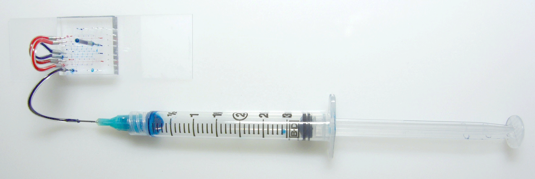
- Load 0.1 mL of the sample into the syringe with the blunt needle and tubing
- Inject into the channels to visualize. Be careful to not introduce bubbles, while air in PDMS leaks out when enough pressure is applied, air has to be flown out from glass devices
- Cure PDMS at 70 C for 1 hour
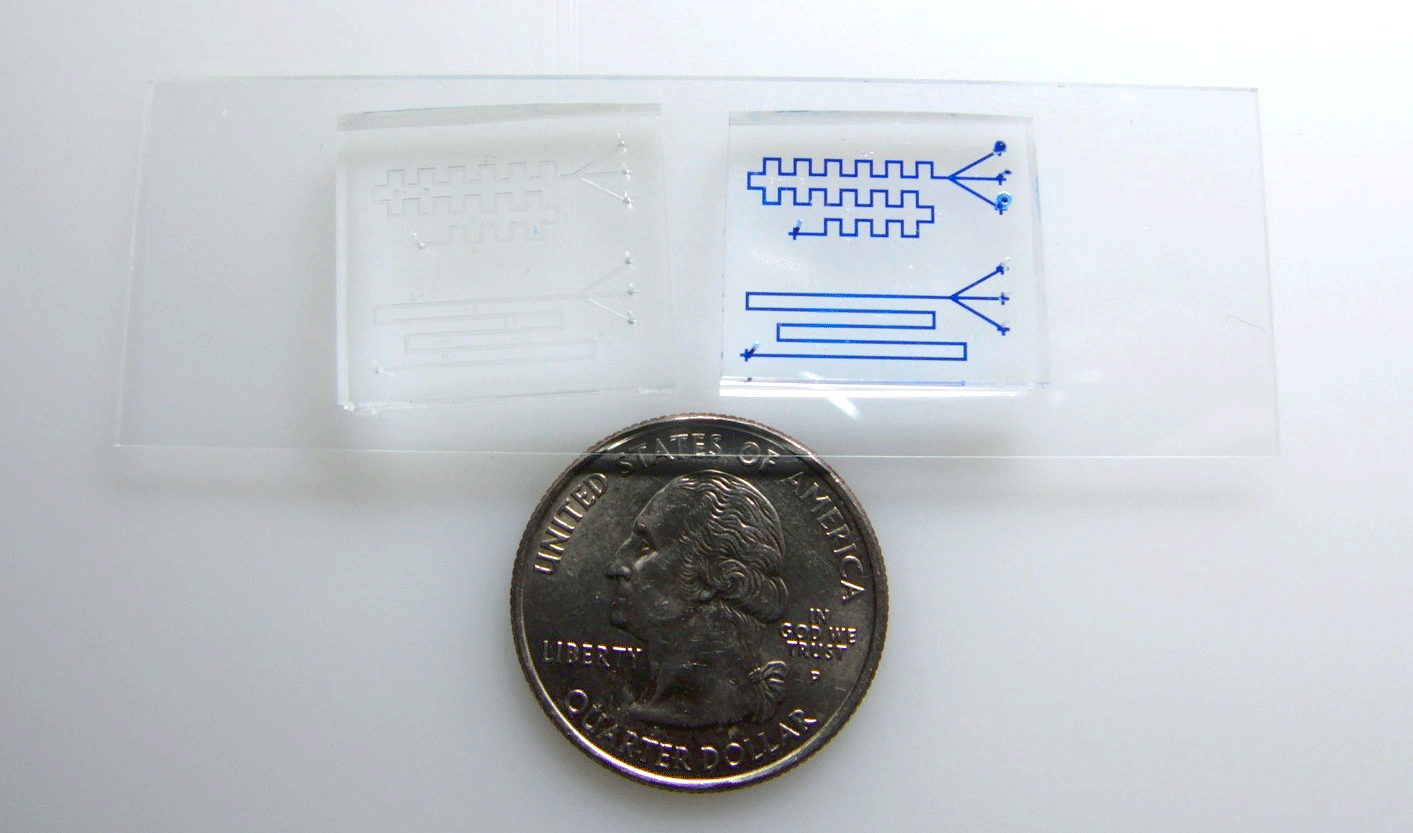
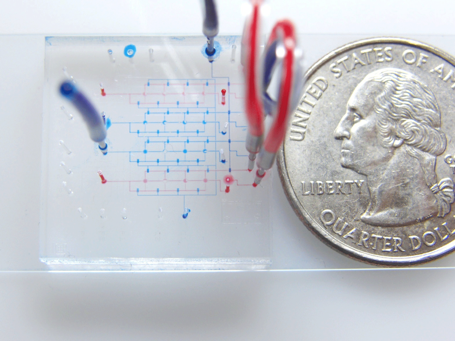
- Devices are ready for display. Notice the enhanced contrast of the colour filled channels vs the empty channels for the same device in Figure 2. While channels are visible only from some directions when they reflect light, colour-PDMS devices can be observed from every direction. Additionally, different device layers or areas can be specified by colour. In the figure control layers are blue and flow layers are red
Fig. 1 Injection of PDMS through the channels. Air trapped inside the syringe provides a way to regulate the pressure applied to the device to minimize de-bonding. Compressing the air to 1/3 of original volume should provide enough pressure to drive the PDMS through.
Fig. 2 Enhanced channel contrast after injection, devices on the left side have empty channels and devices on the right have color PDMS inside.
Fig. 3 Different device zones can be identified by color. Here control layer is blue and flow layer is red. Secondary regulation channels are practically invisible when not filled.
References


