Tiama Hamkins-Indik, Sandra Lam, Megan E. Dueck and Luke P. Lee
Department of Bioengineering, Berkeley Sensor and Actuator Center, Biomolecular Nanotechnology Center, University of California, Berkeley, CA 94720, US
Why is this useful?
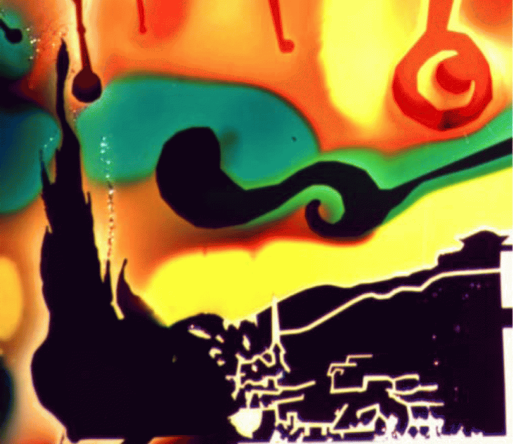
Currently, there is no simple method for aligning multiple layers of PDMS microfluidic devices onto a glass slide. We report a method for alignment that is easy, inexpensive, and has many relevant applications including printing proteins adjacently , flowing cells over previously printed proteins, and aligning two PDMS devices on top of each other for complex 3D geometries . Currently, glass etching can be used to permanently mark glass, but this process is labor intensive and costly . As a proof-of-concept, a 3-layered, 3 mm wide replica of Van Gogh’s Starry Night was created (Figure 5).
What do I need?
1. Permanent marker (e.g. Sharpie™ marker)
2. Syringe (1mL – 10mL) with needle tip (any gauge)
3. Vacuum chamber
4. Light microscope with 4X and 10X objectives
5. Scotch™ Tape
6. Alignment marker
The Alignment Marker:
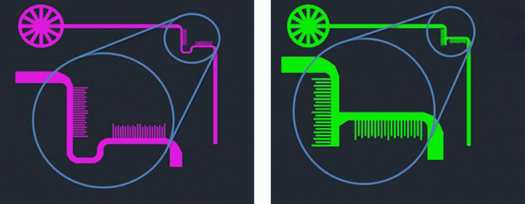
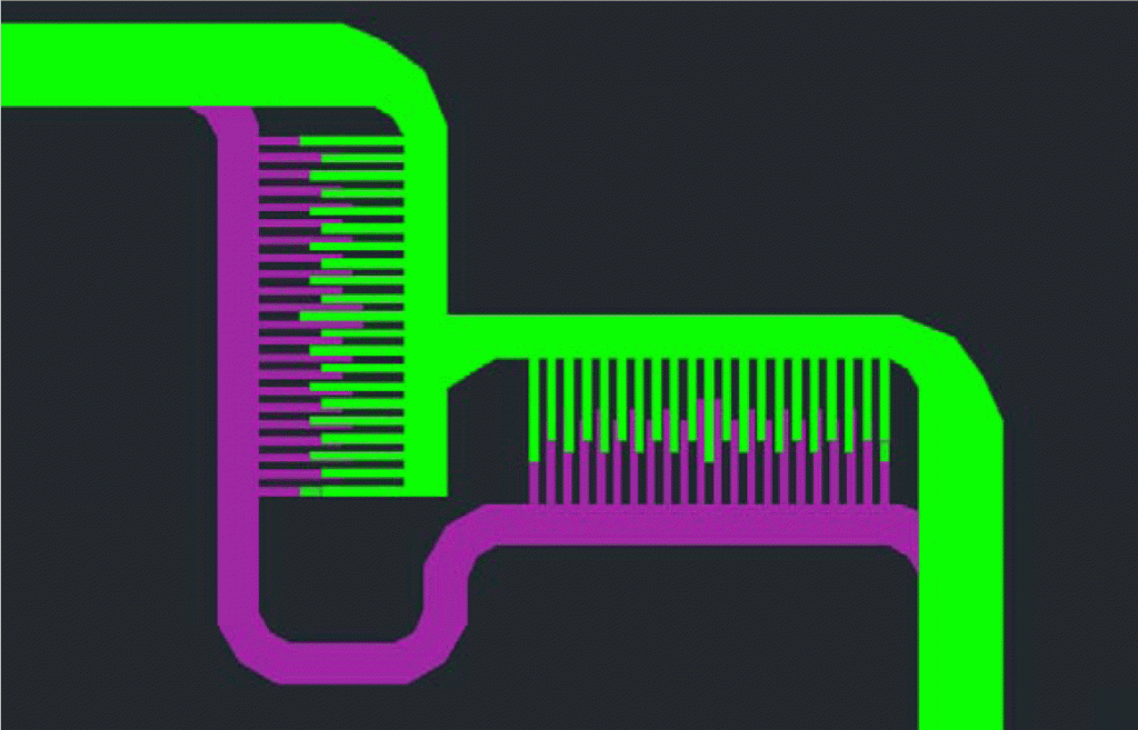
While any alignment marker can be used between layers, we suggest using the one shown in Figure 1. The teeth act as Vernier scales in the x and y directions, thus, the degree of misalignment can be measured. This alignment marker was designed with 10 µm wide teeth. On the first layer (Figure 1, left), there are 22 posts which are 10 µm apart. On the second layer, there are 20 posts each 11µm apart (Figure 1, right), making both markers 430µm wide. The interlocking geometry of the markers is shown in Figure 2. An inlet must be placed on the first layer’s alignment marker so that ink may flow through and stain the glass.
How do I do it?
1. Incorporate alignment marker
- Add the alignment markers into the device design. On the silicon master that will be used to cast PDMS molds, The the channel height of the alignment marker on the silicon wafer should be in the 5 – 200 µm range. The PDMS channel height only needs to be tall enough for Sharpie™ ink to flow through.
2. Sharpie™ Ink Extraction
- Put a needle onto a 1 mL – 10 mL syringe.
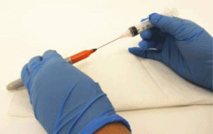
- Insert the needle into the felt tip of a Sharpie™ marker, and slowly pull the plunger. Slow extraction is necessary to allow air to diffuse into the marker as the ink escapes into the syringe. Repeat as necessary. (Figure 3)
- Dispense the Sharpie™ ink into a microcentrifuge tube. Sharpie™ extraction should result in 0.5 – 1 mL of Sharpie™ ink.
- Dilute Sharpie™ ink 3X in 100% ethanol.
3. First Layer
- Cut and punch desired PDMS device.
- Clean a glass slide and the device with Scotch™ tape.
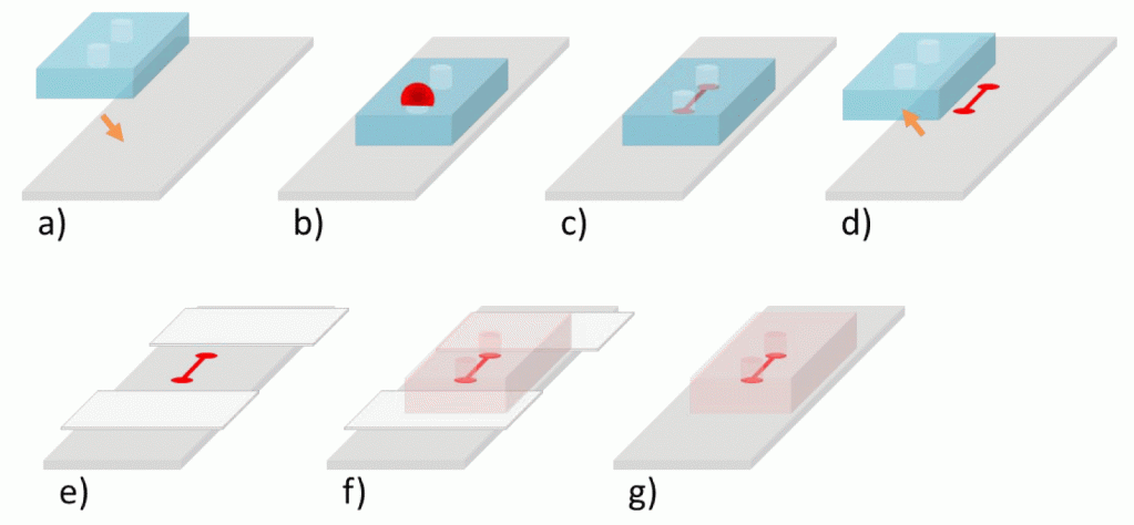
- Reversibly bond the PDMS device onto a glass slide, by simply placing the cleaned PDMS onto the glass slide. (Figure 4a)
- Load the Sharpie™ ink into the alignment marker channel. This can be done by placing the device into a vacuum chamber for 5-10 minutes, removing the device from the vacuum, and placing a ~5 µL drop of Sharpie™ ink over the punch hole. Only punch one entry hole for this method. (Figure 4b)
- Allow the Sharpie™ ink to dry for 2 hours. (Figure 4c)
- Remove PDMS. (Figure 4d)
4. Second Layer
- Cut and punch desired PDMS device.
- Clean device with Scotch™ tape.
- Place Scotch™ tape onto glass slide a few millimeters away from previous design. (Figure 4e)
- Under 4X or 10X magnification, bring the Sharpie™ alignment marker into the center of view and focus slightly above it.
- Carefully place the cleaned second layer onto the scotch tape, but do not press down on the device so that the PDMS device is not in contact with the glass slide.
- Still under the microscope, align the second layer with the Sharpie™ alignment marker by gently pushing the device along the Scotch™ tape. The Scotch™ tape prevents the device from bonding with the glass slide. (Figure 4f)
- Attach the second layer by reversibly binding it to the glass slide by pressing down on the device.
- Remove the scotch tape by holding the middle of the device down and pulling the scotch tape out from the edges of the PDMS device. (Figure 4g)
- If additional layers are necessary, repeat second layer procedure.
What else should I know?
When using this technique by hand, the accuracy of the alignment between two layers can be down to 5 µm. If a more precise alignment is necessary, a six axis alignment machine can be used. As a proof-of-concept, we have reproduced Van Gogh’s Starry Night (Figure 5). This design has two layers, and each layer was filled with Sharpie™ ink using vacuum loading.
References
- Kane et al., Patterning proteins and cells using soft lithogrpahy, Biomaterials, 1999, 20, 2363-2376.
- Natarajan et al., Continuous-flow microfluidic printing of proteins for array-based applications including surface plasmon resonance imaging, Anal. Biochem., 2008, 373 (1), 141-146.
- Chiu et al., Patterned deposition of cells and proteins onto surfaces by using three-dimensional microfluidic systems, Proc. Natl. Acad. Sci. U. S. A., 2000, 97 (6), 2408 -2413.
- 3-Dimensional Molding for Making Microfluidic Devices, MicroDysis – Instrumentation Company with Micro- and Nano-fabrication, and Lab Automation, http://www.microdysis.com/TechMicrofab.aspx, 2010, accessed 16 April 2011.


