Myra T. Koesdjojo*, Jintana Nammoonnoy, and Vincent T. Remcho
Department of Chemistry, Oregon State University, Corvallis, OR 97331
*Corresponding author: Myra T. Koesdjojo
Fax: (541) 737-2062
Email: koesdjom[at]onid.orst.edu
Why is this useful?
Microfluidic systems, also referred to lab-on-a-chip or micro total analysis systems (μTAS) have been developing at a rapid pace in the last decade and offers promising analytical tools that may transform routine chemical analysis in the future. Microfluidic devices typically require multiple interconnects.1 Consequently, reliable microfluidic interconnections have become one of the basic necessities in integrated fluidic and on-chip systems. The lack of an efficient interface or interconnect between microfluidic devices and the macroscale world has historically been a major challenge and one of the greatest limiters on acceptability and the application of μTAS into the broad world market. Clearly, there is a need for a low-cost, flexible interconnects for microfluidic devices to be successful in the long term.2 There are a variety of current products available and techniques that have been used to provide interfacing between microchannels to external devices.3-6 The most common and simplest approach is the direct integration of tubing or a syringe needle into the microchip inlet using epoxy glue. The drawback is it often leads to clogging of the microchannels and these types of interconnections are impractical to remove and are not reusable. This tip presents a simple method to making reusable quick release magnetic-based fluidic connectors. It is an alternative approach that provides a simple, cost effective universal interconnects in the microfluidic applications. The magnetic-based connectors was developed using two permanent magnets that form a compression seal against the tubing line and the surface of the microfluidic device. The magnetic connector also allow for standard tubing to be interfaced with the microchips. With this approach, interconnects can be easily assembled and reconfigured numerous times without causing damage to the microfluidic device. And since connection is established though a magnetic based approach, clogging of microchannels from adhesive or epoxy can be avoided.
What do I need?
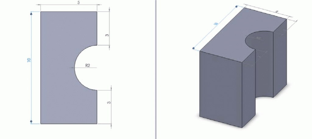
- Permanent magnets (design and dimension shown in Figure 2)
- Magnetic base
- Elastic such as PDMS compression seals or vacuum cup
- PEEK or Teflon tubing (not limited to the materials of the tubing)
What do I do?
1. Custom made permanent magnet shown in Figure 2. The first component was a permanent magnet that allowed for a standard tubing to be attached to a microfluidic device via a flexible compression seal. It was manufactured with the dimensions shown below to provide a tight fitting to the flexible seal when sandwiched between two magnets, which in turns compressing the tubing inside. The magnets are Neodymium magnets which are over ten times stronger than the ceramic magnets. These magnets are ideal for use as interconnects since they provide much greater holding forces. They can be purchased from Indigo Instruments or K&J Magnetics.
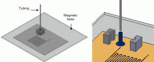
2. Rubber cup compression seals The second component was a flexible rubber cup or compression seals. The dimension should be optimized so that the inner diameter of the seal should provide a tight fitting for a tubing (a in Figure 3b) and the outer diameter (b) is slightly larger than the magnets core so when it is sandwiched in between the two magnets, the tubing is tightly held. The last parameter is the diameter of the lip base (c), which should be larger than the magnet’s core so it can be compressed to the magnetic base and tightly secured against the microchip surface to prevent leaking. A variety selection of compression seal (vacuum cup) with different sizes can be purchased from McMaster-Carr.
3. A magnetic base was used which applied pressure between the microfluidic chip and the interconnects (Figure 4). The base is particularly useful for microchip and devices having different dimensions and port locations, as the interconnects could easily be relocated.
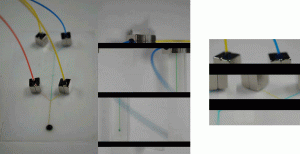
4. The magnetic interconnects were placed on each of the reservoir holes of the microchip to test for leaking.
References
[1] T. Das, D. Chakraborty and S. Chakraborty, Interfacing of microfluidic devices, Chips & Tips (Lab on a Chip), 27 February 2009.
[2] IEEE Trans. On Adv. Packaging., 2003, 26 (3), 242-247.
[3] J. Greener, W. Li, D. Voicu and E. Kumacheva, Reusable, robust NanoPort connections to PDMS chips, Chips & Tips (Lab on a Chip), 8 October 2008.
[4] http://www.upchurch.com/
[5] www.labsmith.com/microfluidicsinterconnects.html
[6] J. Micromech. Microeng., 2005, 15, 928-934.
Reusable Magnetic Connector for Easy Microchip Interconnects


