Steve C.C. Shih1, 2 and Aaron R. Wheeler1, 2, 3
1 Institute for Biomaterials and Biomedical Engineering, University of Toronto, 164 College St., Toronto, ON, M5S 3G9
2 Donnelly Centre for Cellular and Biomolecular Research, 160 College St., Toronto, ON, M5S 3E1
3 Department of Chemistry, University of Toronto, 80 St George St., Toronto, ON, M5S 3H6
Why is this useful?
Digital microfluidics (DMF) is a technique in which discrete droplets are manipulated by applying electrical fields to an array of electrodes.1 An advantage of DMF is that droplets serve as discrete microvessels in which reactions can be carried out without cross-talk between samples or reagents. In contrast to the more conventional geometry of enclosed microchannels, each sample on a DMF device can be addressed individually, and reagents can be dispensed from reservoirs, moved, merged and split.2
A key component in a functioning DMF device is the insulating layer (i.e., a dielectric material) which is deposited on top of the actuation electrodes to facilitate the build-up of charge which drives droplet actuation.3 Fabrication of dielectric layers can be time-consuming and the costs for depositing them can be very expensive (e.g., a common method is chemical vapour deposition of parylene C). Alternative methods have been described,4 but in all previous work, a separate dielectric layer must be positioned onto a device.
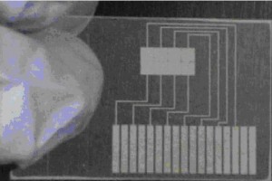
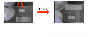
Here, we report a new method which we have called “DMF Flip-Chips,” in which the device substrate itself serves as the dielectric layer. In this method, actuation electrodes are patterned on one side of a glass coverslip (or other thin substrate), which is then flipped over such that the substrate serves as the insulating layer for droplet manipulation. This method is faster than conventional fabrication, and we speculate it will be useful for laboratories that do not have a dielectric coater but would like to use digital microfluidics.
What do I need?
- Glass coverslips with thickness of 160 mu.gifm or less
- Indium-tin-oxide coated glass (Delta Technologies Ltd, Stillwater, MN) to serve as top substrate
- Scissors
- Double-sided tape
- Teflon-AF
How do I do it?
1. Pattern a glass coverslip with an array of electrodes. This can be accomplished using conventional cleanroom techniques2,3 or by rapid prototyping techniques such as microcontact printing,5 laser toner printing,6 or marker masking.7
2. Flip the substrate over and coat the “bottom” (now top) with Teflon-AF as described previously. Likewise, coat an ITO-glass substrate with Teflon-AF.2,3
3. Assemble the device with the patterned glass substrate on the bottom, double-sided tape spacers in the middle, and ITO-glass substrate on the top. Sandwich droplets between the two substrates.
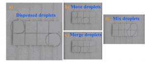
4. Apply driving potentials (~500 VRMS and 15 kHz) between electrodes on the bottom and top plates, which causes droplets to a) dispense, b) move, c) merge, and d) mix as shown.
What else should I know?
- Potentials of ~500 VRMS are appropriate for bottom plates formed from a 160 mu.gifm coverslip. Lower potentials can be used with thinner coverslips.
- Additionally, lower voltages can be used for substrates formed from materials with higher dielectric constants than glass.
- Clean surfaces with methanol or water after every use.
- Thinner cover slips are difficult to use because they are very brittle and fragile.
Acknowledgements
We thank Irena Barbulovic-Nad for helpful discussions.
References
[1] A. R. Wheeler, Science, 2008, 322, 539-540.
[2] S. K. Cho, H. J. Moon and C. J. Kim, Journal of Microelectromechanical Systems, 2003, 12, 70-80.
[3] M. G. Pollack, A. D. Shenderov and R. B. Fair, Lab Chip, 2002, 2, 96-101.
[4] M. J. Jebrail, N. Lafreniere, H. Yang and A. R. Wheeler, A two-for-one dielectric and hydrophobic layer for digital microfluidics, Chips & Tips (Lab on a Chip), 6 July 2010.
[5] M. W. Watson, M. Abdelgawad, G. Ye, N. Yonson, J. Trottier and A. R. Wheeler, Anal. Chem., 2006, 78, 7877-7885.
[6] M. Abdelgawad and A. R. Wheeler, Adv. Mat., 2007, 19, 133-137.
[7] M. Abdelgawad and A. R. Wheeler, Microfluid. Nanofluid., 2008, 4, 349-355.


