Koesdjojo, M.T., Mandrell, D.T., Tennico, Y.H., Remcho, V.T.*
Department of Chemistry, Oregon State University, Corvallis, Oregon, USA
Why is this useful?
The lack of an efficient interface, or interconnect, between microfluidic devices and the macroscale world is a major impediment to the broader application of micro total analysis system (µTAS). There are a number of current products and solutions available that seek to address this issue. An example of a simple approach is the direct integration of tubing or a syringe needle into the microchip inlet using epoxy glue.[1] However, direct connection to the inlet reservoir using an epoxy often leads to clogging of the microchannels. Commercially available connections to microfluidic chips and devices, such as the NanoPort from Upchurch Scientific (Oak Harbor, WA, 98277, USA), accommodate these needs by use of a threaded nut and ferrule system. These fittings can be integrated onto chip reservoirs by means of adhesive rings or epoxy glue.[2] The drawback to this method is that NanoPorts require the use of an epoxy glue that takes time to cure and is non-removable, or an adhesive ring that is not compatible with many solvents. Another drawback is that the epoxy requires high temperatures for complete curing, making it incompatible with low glass transition (Tg) polymers.[3] Commercial edge connectors provide efficient interfacing and allow rapid connections and reusability.[4] However, they are designed to be interfaced to a standard microchip format; which limits the compatibility of other chips with different geometries layout or sizes.
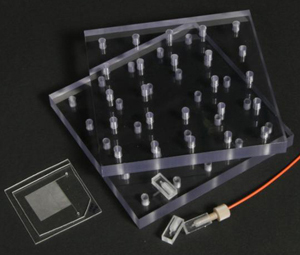
This tip presents an alternative approach to making simple, cost-effective universal interconnects. The device was developed to allow for standard compression tubing connectors, such as those available from Upchurch, to be interfaced with microfluidic chips. A standard breadboard fixture was used to compress the ports against the chip to apply sealing pressure, preventing leaks at the interface. This method allowed for connections to be made without glue, epoxy, or any form of bonding, enabling the components to be easily and quickly reused or reconfigured without the need to machine new fixtures or re-bond ports. The working pressure of these ports was tested with a syringe pump, and withstood pressures in excess of 1000 psi without any signs of leakage or failure.
What do I need?
- 0.25 and 0.5 inch thick plastic substrates such as polycarbonate (PC)
- #21, #9 drill bits
- 10-32 bottoming tap
- 1mm drill bit
- 1/16 inch PEEK or Teflon tubing
- stainless steel 10-32 socket head cap screws
- 1/32 inch Silicon o-rings
- Upchurch 10-32 ferruled fittings (F-333)
What do I do?
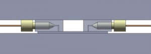
1. The first component was a port which allowed a standard ferruled connector to be attached perpendicular to the microfluidic device. It contained a threaded portion for the fitting and a fluid path with small port on the bottom for the interface (Figure 2). The port was manufactured using 0.25 inch PC, but can be made of any material thick enough to allow room for the ferruled connector between the compression plates. It was machined to size using a knee mill. The threaded port was drilled with a #21 drill bit, then tapped with a 10-32 bottoming tap. The fluid paths were drilled using a 1mm drill bit (substitute any drill to achieve the desired internal volume). An o-ring was then placed in the threaded hole to ensure a tight seal against the ferruled fitting.
2. The second component was a breadboard clamp which applied pressure between the microfluidic device and interconnects (Figure 3). This breadboard approach was particularly useful for prototyping devices having different dimensions and port locations, as interconnects could easily be relocated. A wide variety of bolt locations in the clamping plates allowed for a wide variety of component sizes and configurations. The breadboard clamp assembly was manufactured by cutting 0.5 inch thick PC into two five inch squares. Using the knee mill, a one inch grid of holes was drilled and taped on one plate with the #21 drill and 10-32 tap. Clearance holes were drilled on the same grid, using a #9 drill bit, in the second clamping plate.
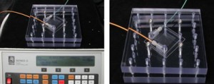
3. The 90° interconnect ports were placed on each of the reservoir holes of a microchip. The ferrules were connected to their respective tubing. The top plate of the breadboard clamp was installed and using the holes closest to the sides of the chip, 10-32 stainless steel screws were inserted to apply even pressure by clamping the entire fixture. Figure 4 shows the setup used to pressure-test the manufactured ports.
References
[1] T. Das, Interfacing of microfluidic devices, Chips & Tips (Lab on a Chip), 27 February 2009.
[2] http://www.upchurch.com/
[3] J. Greener, W. Li, D. Voicu, E. Kumacheva, Reusable, robust NanoPort connections to PDMS chips, Chips & Tips (Lab on a Chip), 8 October 2008.
[4] http://www.dolomite-microfluidics.com/


