Rachel Green and Siva A. Vanapalli
Department of Chemical Engineering, Texas Tech University, Lubbock, TX, USA
Why is this useful?
Syringe pumps are often used in a variety of microfluidic applications because of their portability and the ease with which flow rates can be changed. The syringe pump characteristics (type, age and wear), compliance in the tubing, a mismatch between the size of syringe used and the flow rate desired can generate pulsations in microfluidlic flows. These pulsations could be undesirable for lab-on-a-chip applications in which steady fluid flows are needed. The method described here is a quick means to assess the degree of pulsations present in flows driven by syringe pumps. The basic principle relies on using a microfluidic comparator [1,2] to detect small pressure fluctuations in fluid flows.
What do I need?
- Microfluidic device with design as shown in Figure 2.
- Ring stand
- Ring stand clamp
- Syringe pump
- Distilled water
- Dyed distilled water (refill ink)
- Syringe (30 or 60 mL)
- Tubing
- Stereomicroscope
What do I do?
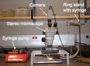
1. Set up ring stand with a wide-mouth syringe in the ring stand clamp (Figure 1). This is your hydrostatic head. The distilled water will go in this syringe.
2. Place a syringe with the dyed distilled water into the syringe pump.
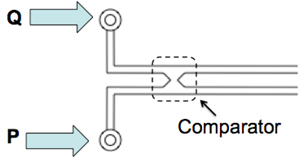
3. As shown in Figure 2, connect the syringe pump to the chip (labeled as flow rate Q). Connect the hydrostatic head, P, from the ring stand to the chip.
The outlets are open to atmospheric pressure. The device consists of two identical channels connected downstream to form a comparator region. At one inlet we impose a constant hydrostatic pressure (P) to generate steady flow and in the other inlet we use a syringe pump to introduce fluid admixed with a dye at a flow rate, Q.
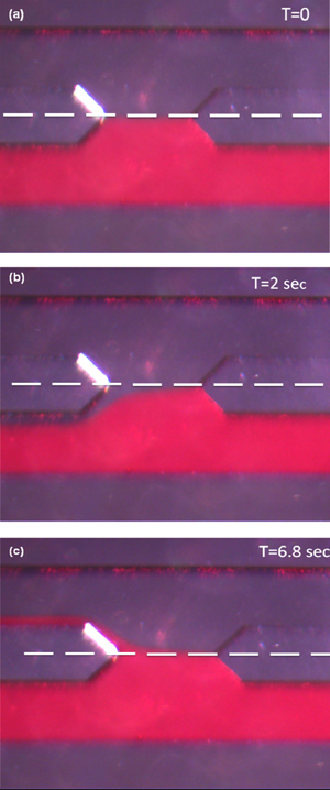
4. Start the syringe pump at the desired flow rate. Vary the height of the hydrostatic head until the two fluid flows meet at the symmetry line of the comparator (see the white line in Figure 3a).
5. Because the hydrodynamic resistances of the two channels are equal, if any pulsations are present in the syringe-pump driven flow then the dyed fluid will be displaced above or below the symmetry line (shown in white) in the comparator, as shown in Figure 3b and 3c.
(a) The flows are steady and balanced. (b) After a time interval of 2 seconds, the dyed fluid is below the symmetry line indicating the syringe pump flow rate is lower than the flow rate corresponding to the imposed hydrostatic pressure. (c) After 6.8 seconds, the dyed fluid flow is above the symmetry line, indicating the syringe pump flow rate is greater than the flow rate corresponding to the imposed hydrostatic pressure.
What else should I know?
The method described is a quick assessment of the pulsations generated by syringe pump driven flow. For a more in depth study, we recommend using a precision hydrostatic head rather than a ring stand. We built a stand that can hold a syringe on a precision linear translation stage (Edmund Optics, Part # NT56-796). The stage allows the hydrostatic head to be adjusted at 0.1 mm intervals. Using this hydrostatic head and a video camera, one can precisely determine the number of fluctuations per unit time for a specified pump, flow rate, syringe size and tubing.
References
1. M. Abkarian, M. Faivre and H. A. Stone, Proc. Natl. Acad. Sci., 2006, 103, 538-542
2. S. A. Vanapalli, D. van den Ende, M. H. G. Duits and F. Mugele, Appl. Phys. Lett., 2007, 90, 114109


