T. Liu, E. V. Moiseeva, and C. K. Harnett
Electrical and Computer Engineering, University of Louisville, Louisville, KY 40208, USA
Purpose
Reservoirs are sometimes preferable to tubing connections, especially for pressurized or gravity-driven flow, for installing electrode wires into open ports, or for storing a PDMS chip pre-loaded with water to preserve its hydrophilicity after plasma treatment. However, gluing individual reservoirs onto a finished chip can be messy and prone to clogging ports and channels with silicone, and the assembly may be fragile. These reservoirs, made from inexpensive nylon spacers, are embedded in the chip by PDMS casting, eliminating several of these problems. They can run with up to 30 psi gas pressure-driven flow when provided with connections for pressurized tubing.
Materials
Consumables:
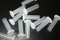
- Flanged nylon shoulder spacers (McMaster Carr part 91145A154, shown in Figure 1)
- PDMS compound (Dow Corning Sylgard 182 or 184)
For optional gas pressure-driven flow:
- Epoxy (Scotch-Weld DP-420)
- Hose barb connectors (McMasterCarr part 51525K211)
Tools:
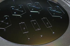
- A mold for casting chips (Figure 2)
- PDMS weighing and degassing equipment
- A punching tool for creating ports in PDMS, such as thin-walled stainless hypodermic Tubing (Small Parts Inc., part HTX-22X or similar)
- Tweezers
- X-Acto knife
Procedure
1. Make a mold for your design, with reservoir locations 1 cm apart or more. This method was tested on SU-8 molds on silicon wafers, with resist thickness from 60 to 170 microns, without any special mold release treatment.
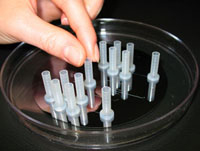
Pour a thin (~1 mm) layer of PDMS over the mold, and cure until solid. Place the nylon standoffs on top of the PDMS layer, over the ends of your channels, flange side down. Later you will punch to connect the reservoir with the channel on the underside of the chip. These reservoirs easily stay upright if the PDMS is still a bit sticky. (Figure 3)
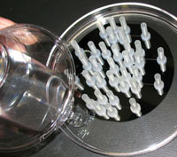
2. Pour a second 2 mm or thicker layer of PDMS around the reservoirs, covering the flanges to anchor them. (Figure 4) It doesn’t matter if PDMS seeps into some of the reservoirs. Let the PDMS level out, then cure until solid. The nylon reservoirs are OK at temperatures up to 80ºC.
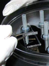
3. Cut out individual devices with the X-Acto knife and peel off devices plus embedded reservoirs. It’s best to grip the devices at the PDMS using tweezers, rather than pulling on the reservoirs. (Figure 5)
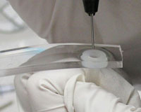
4. Use the punching tool to create a port in each reservoir that connects to the microfluidic channel, making sure to remove a core of PDMS from each port. This can be done from the channel side (Figure 6) or from the reservoir side.
5. Bond the punched chips to a glass, PDMS or other substrate using plasma activation or other method of choice. Figure 7 is a side view of a bonded chip, showing anchored reservoirs and punched ports on a molded PDMS chip, attached to a blank PDMS slab on a glass slide.
6. (Optional, for gas pressure-driven flow) Use epoxy to attach hose-barb connectors to the tops of any reservoirs you want to pressurize. Gas can be provided to each reservoir using Tygon tubing. The 1/16″ hose barb to Luer connectors, and 1/16″ ID Tygon tubing are a good match to the size of these reservoirs. Gluing adjacent Luer connectors together can help strengthen the assembly when several gas connections are anticipated.
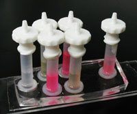
7. Fill reservoirs through the open tops or through the bonded-on hose barbs. Dispensing from a syringe with a long needle or a needle threaded into a small diameter piece of tubing helps prevent trapped air by filling from the bottom up. Figure 8 shows a filled chip with barbs for gas tubes.
8. While these reservoirs have been pressurized up to 30 psi before delaminating, they are easily removed from the chip by bending them sideways. Reservoirs can be peeled out of old chips for re-use if needed.


