Corey Koch, James Ingle, and Vincent Remcho
Department of Chemistry, Oregon State University, Corvallis, Oregon, USA
Why is this useful?
The formation of vias between microchannels in PDMS and fluidic interconnects is commonly performed by using a punch to cut away PDMS. This process often results in a torn surface that is not as resilient to pressure driven flow, can create material that clogs channels, provides less control of hole shape, and results in the formation of irregular surfaces that increase dead volume.[1] A smoother surface finish and more controllable hole geometries have been achieved by using posts in the molding process.[2] Magnetic fixturing of via holes provides a readily configurable and facile means to locate and hold posts. Magnets also come in all shapes and sizes and can therefore provide a creative means to incorporate mesoscale features into PDMS microchips. In this example, cylindrical neodymium magnets are used to mold via holes into a PDMS microchip.
What do I need?
- Magnets for molding. Neodymium magnets provide the strongest field and are available commercially in a variety of shapes and sizes.
- A microchip master mold. Guide features on the microchip master can aid magnet alignment.
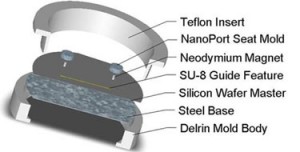
- A PDMS molding fixture that can attract magnets. A mold made from a ferromagnetic material (such as steel) or placing a magnetic base below a plastic or aluminum fixture, as shown in Figure 1, can provide a means to hold the magnets.
- PDMS (Dow Corning Sylgard 184).
- In this example, a flat surface was necessary above the via hole to bond Upchurch NanoPorts as interconnects. Because PDMS forms a meniscus on the surface around the magnet when curing, a steel cylinder was placed above the via hole molding magnet to create a NanoPort mating seat.
What do I do?
1. Prepare your master mold, magnetic PDMS mold (An SU-8 on silicon microchip master mold and steel base are shown as an example in Figure 2), and your magnets.
2. Place the magnets on the appropriate guide features on the master mold as shown in Figure 3. In this example 1/8″ high by 1/16″ diameter cylindrical magnets and a specially designed plastic mold with a steel base (as shown in Figure 1) were used. An aluminum foil mold as described in “Chips and Tips: Rapid curing of PDMS for microfluidic applications” could be used for a quick and easy molding platform.
3. In this example a flat surface is needed for bonding Upchurch NanoPorts, so a steel cylinder (Figure 4) with a diameter greater than the NanoPort is placed on top of the magnet to move the PDMS meniscus away from the center of the via hole and provide a flat seat for bonding.
4. Pour the PDMS as shown in Figure 5 (mixed to manufacturer specifications or for your specialty application). Bubbles can get trapped under the steel ‘NanoPort seat’ so fill the mold slowly or degas after filling.
5. Cure the PDMS at your desired temperature. Remove the PDMS from the mold and use a tweezers to pull out the magnet. Cut the chip to size as shown in Figure 6 and notice the quality of your now ready via hole!
6. In this example, the steel ‘NanoPort seat’ provided a flat surface to bond the NanoPort, and the meniscus actually allows for rapid registration of the NanoPort to the via hole (Figure 7). The 1/8″ high by 1/16″ diameter magnets used can be placed close enough for maximum NanoPort packing density (magnets within 5 mm of each other).
Using magnetic posts can provide a variety of shapes and sizes of via holes, a smooth hole, and a convenient method for securing posts during molding.
Another quick tip for using 1/16″ tubing: employ 1/16″ diameter cylindrical magnets and tubing with a small ID. Cut the tubing at a slight angle and insert it to the bottom of the via hole to minimize dead volumes in your interconnect.
Acknowledgements
This material is based upon work supported by the National Science Foundation under Grant No. DGE-0549503. This research was also supported by a research grant from the U.S. Environmental Protection Agency sponsored Western Region Hazardous Substance Research Center under agreement R-828772. This work has not been reviewed by the agency, and no official endorsement should be inferred. We would like to recognize Ted Hinke at the Oregon State University Department of Chemistry Machine shop for his help in mold design and his skill in its construction.
References
1] S. Li and S. Chen, IEEE Transactions on Advanced Packaging, 2003, 26, 242-247.
[2] D. C. Duffy, J. C. McDonald, O. J. A. Schueller and G. M. Whitesides, Anal. Chem., 1998, 70, 4974-4984.


