Archive for the ‘On-chip features’ Category

Easy and reversible connection with patafix for a pressure flow control system

Ayako Yamada, Fanny Barbaud, Yong Chen, and Damien Baigl
Department of Chemistry, Ecole Normale Superieure, Paris, France

Why is this useful?


Controlling flows in a microfluidic channel by gas pressure is sometimes preferable due to the stability and quick response of flows. Here we describe an easy way of connection between a sample reservoir and tubing connected to a pressure regulator without gas leakage. With our tips, one can quickly prepare a sample reservoir; one can easily open and close it to refill during experiments; one can easily disassemble, clean, and reuse the system, if necessary. It is also possible to manage a small volume sample (e.g., 5 µL) by employing a micropipette tip.

What do I need?


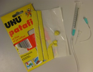
1. Patafix from UHU GmbH & Co. KG (Baden, Germany)
2. Plastic syringe without plunger (for a large volume sample; e.g., 100 – 1000 µL)
3. Needle for the syringe without pointed tip (for a large volume sample; e.g., 100 – 1000 µL)
4. Micropipette filter tip (for a small volume sample; e.g., 5 µL)
5. Tubing
6. Compressed air
7. Pressure regulator
8. PDMS channel


For a large volume sample (e.g., 100 – 1000 µL)


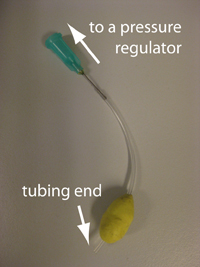
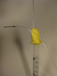
1. Wrap patafix around tubing to make a ball of approximately 1.5 cm diameter, leaving 5 mm from the tubing end (Fig. 1). The other end is to be connected with a pressure regulator. Put suitable accessories for your system.

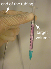
2. Connect a plastic syringe, a needle, and tubing. Hold the other end of the tubing, which is to be connected with your microfluidic channel, higher than the target volume in the syringe. Then fill the syringe with your sample using a micropipette (Fig. 2). Remove air bubbles by tapping, if necessary.

Figure 1

Figure 2

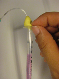
3. Insert the tubing with patafix prepared in step 1 to the open part of the syringe. Then squeeze the patafix into the syringe with your fingers so that about 5 mm of the syringe becomes filled (Fig. 3).

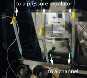
4. You can keep the tubing end accesible by sticking it on the patafix ball (Fig. 4). Connect the syring tubing to the pressure regulator keeping the syringe vertical. Following this way, your sample never touches patafix. It is convenient to place the pressure regulator high enough so that you can hang up the syringe from the regulator and maintain it vertical.

Figure 3

Figure 4

5. Connect the tubing with your channel and apply pressure (Fig. 5). This system can withstand operating pressures up to about 700 mbar (gauge pressure). You can open it by pulling the patafix out of the syringe, and easily refil with the sample, if necessary. If the tubing end is buried in patafix, simply tear off patafix until the tubing end appears. It is better not to try to dig patafix. It makes patafix go inside the tubing.

Figure 5

For a small volume sample (e.g., 5 µL)


1. Same as the step 1 described above, except that the diameter of the patafix ball should be about 2 cm.

2. Take your sample by micropipette. A pipette tip with a filter is preferable.

3. Remove the tip from the micropipette. If air comes up into the tip, you can get rid of it by tapping the tip gently until your sample goes back to the tip end. Then insert the tip into a PDMS channel inlet (we make inlet holes by punching through the PDMS with a syringe needle without a pointed tip and cleaning with isopropanol) (Fig. 6).

Figure 6

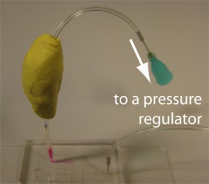
4. Connect the tubing and patafix prepared in the step 1 with the pipette tip. Try to make a homogeneous thickness (about 5 mm) layer of patafix around the connection and seal well (Fig. 7). Connect them to the pressure regulator and apply pressure. This system can withstand operating pressures up to about 300 mbar (gauge pressure).

Figure 7
Digg This
Reddit This
Stumble Now!
Share on Facebook
Bookmark this on Delicious
Share on LinkedIn
Bookmark this on Technorati
Post on Twitter
Google Buzz (aka. Google Reader)

Organic solvent compatible reservoirs for glass microfluidic chips

Michael W. L. Watson and Aaron R. Wheeler
Department of Chemistry, University of Toronto, Ontario, Canada

Why is this useful?


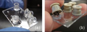
Some applications for microfluidics, such as synthesis, reversed phase separations, and liquid-liquid extraction, require the use of organic solvents (e.g. acetonitrile, methanol, etc.).  For such applications, glass or quartz substrates are preferred; however, even when using solvent-resistant substrates, such applications are often limited by the problem of connecting reservoirs to the substrate. As illustrated in Figure 1, common adhesives used for this purpose, such as epoxies and UV cured glues, are not able to withstand extended periods of exposure to solutions with high organic solvent content.

Figure 1: Reservoirs connected with traditional adhesives

In this Tip, we report a straightforward solution to this problem: using an oxygen plasma bonded poly(dimethyl siloxane) (PDMS) reservoir manifold (Figure 2).

Figure 2: An organic solvent compatible reservoir

This structure is inexpensive, easy to apply, and is able to withstand a wide range of organic solvents for periods of up to several weeks.

What do I need?


  • PDMS.   We use the Sylgard 184 PDMS kit   (Dow Corning Company), but any of a variety of PDMS formulations could be used.
  • Vacuum chamber.   An air-tight chamber that can be attached to a pump or house vacuum.   We use a vacuum oven (Fisher Scientific Model 280A).
  • Oven.   PDMS can be cured at room temperature overnight, but the process is much faster in an oven.
  • Plasma cleaner.   We use a Harrick Plasma cleaner (Model PDC-001) to pre-treat glass and PDMS surfaces prior to bonding.   An air plasma can be used but an oxygen plasma will yield a better seal.
  • Glass microfluidic chip. Home-made or purchased glass or quartz microfluidic devices are required for work with strong organic solvents. We purchase chips from Caliper Life Sciences.
  • Hole punch or coring tool. The reservoir volume is determined by the diameter of the holes in the manifold.   We use either a coring tool with a diameter of 2 mm or a paper hole punch with a diameter of 5 mm.

What do I do?


  1. Mix PDMS and curing agent in a 10:1 weight ratio in a disposable weigh boat.
  2. Degas PDMS under vacuum.
  3. Pour the PDMS into a plastic Petri dish to a depth of about 3-4 mm.
  4. Cure PDMS for 1 hour at 70oC.
  5. Cut the PDMS with a scalpel to fit the shape of the microfluidic device.
  6. Punch holes through the PDMS such that they line up with the inlet ports in the microfluidic device. (For alignment, fit the PDMS manifold to the glass surface and use a Sharpie to mark the locations of the holes, prior to bonding, test-fit the manifold to ensure that the punched holes align with the microfluidic inlet ports.)
  7. Clean the glass device and manifold with deionized water and isopropanol and dry under a stream of nitrogen.
  8. Plasma treat the surfaces to be bonded under oxygen (5 psi O2, 400 mtorr vacuum, 26.9 W, 90 s).
  9. Bring the two surfaces together.  Press down firmly for 20-30 s to ensure good seal formation.
  10. After use, the glass chip can be recycled by removing the PDMS slab with a razor blade and cleaning with acetone.

What else should I know?


These reservoirs provide a transparent alternative to opaque adhesives making it easier to visualize networks of channels and use optical detection methods. While some swelling is observed in solvents such as acetonitrile, the seal between the PDMS and glass does not leak, allowing for weeks of continued exposure to organic solvents. Note that highly aggressive solvents such as ethers or benzene are not compatible with this method.

Digg This
Reddit This
Stumble Now!
Share on Facebook
Bookmark this on Delicious
Share on LinkedIn
Bookmark this on Technorati
Post on Twitter
Google Buzz (aka. Google Reader)

On-chip electrophoresis devices: do’s, don’ts and dooms

Alexandre Persat, Tom Zangle, Jonathan Posner and Juan Santiago
Stanford Microfluidics Laboratory, Department of Mechanical Engineering, Stanford University, Stanford, CA

Background


On-chip electrokinetic injections and on-chip electrophoresis are well-established techniques, and the field is about 15 years old [1].The techniques for on-chip sample loading, voltage control, injection, separation, visualization, and electropherogram detection have been described in numerous publications [2, 3]; a few of these are summarized by Sharp et al. [4].

Below we present a few informal “tips” listed under various categories that we hope may be useful to new users of this technology.  These instructions are in no way comprehensive, are not even quantitative, but we hope they will save someone somewhere some time.

References


1. A. Manz, D. J. Harrison, E. M. J. Verpoorte, J. C. Fettinger, A. Paulus, H. Ludi and H. M. Widmer, J. Chromatogr., 1992, 593(1-2), 253-258.
2. A. Manz, C. S. Effenhauser, N. Burggraf, D. J. Harrison, K. Seiler and K. Fluri, J. Micromech. Microeng., 1994, 4(4), 257-265.
3. G. J. M. Bruin, Electrophoresis, 2000, 21(18), 3931-3951.
4. K. V. Sharp, R. J. Adrian, J. G. Santiago and J. I. Molho, “Liquid Flows in Microchannels” (updated), in CRC Handbook of MEMS, CRC Press, 2006, Boca Raton, Florida, USA.

Digg This
Reddit This
Stumble Now!
Share on Facebook
Bookmark this on Delicious
Share on LinkedIn
Bookmark this on Technorati
Post on Twitter
Google Buzz (aka. Google Reader)