Ya-Yu Chiang, Nikolay Dimov, Nicolas Szita
Department of Biochemical Engineering, University College London, London, United Kingdom
E-mail: n.szita@ucl.ac.uk
Why is this useful?
The packaging of micro-systems relies strongly on the capability to bond different types of materials reliably whilst maintaining the microstructures and their dimensions. However, the bonding of different materials each with their specific physical and chemical properties frequently turns into a tedious, thus time consuming operation; often, the choice of materials and microfabrication techniques are limited by the bonding technique. Particularly challenging for bonding can be combinations of quartz, glass or silicon with polymers and metals.
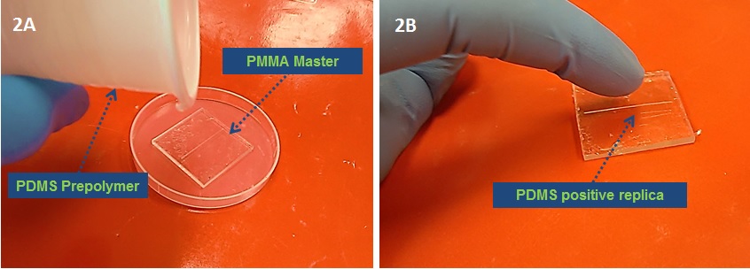
Here we demonstrate a rapid, low-cost, UV-irradiation based bonding method, which is suitable for the bonding and assembly of quartz-to-silicon, quartz-to-metal, quartz-to-polymer, quartz-to-quartz devices. We demonstrate in detail on the more challenging combinations, namely the bonding of a quartz slide to an aluminum sheet. In our example, the aluminum sheet contains the microfabricated structure. The same procedure is applicable for the other material combinations, i.e. quartz-to-silicon, quartz-to-polymer, quartz-to-quartz or quartz-to-metal for a metal other than aluminium; the main requirement for implementing our method is that at least one material is transparent to UV light.
What do I need?
- Aluminum sheets, thickness of 1 mm (e.g. AW6082-T6, Smiths Metal Centres, UK)
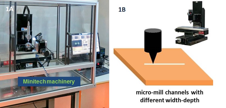
- Micro milling machine (e.g. CNC MicroMill GT, Minitech, US)
- Flat head end-mills 0.25 mm, and 2 mm (e.g. PMT Endmill, US)
- Plasma Cleaner (e.g. PDC-32G-2, Harrick Plasma, UK)
- UV-curing adhesive (e.g. NOA 61, Noland Products, UK)
- UV lamp, 100 W, 365 nm (e.g. B-100 AP, UVP, Cambridge, UK)
- Quartz microscope slide, fused quartz, 25.4 × 76.2 x 1 mm3 (e.g. 42297, Alfa Aesar, UK)
What do I do?
1. Device design and leveling of the metal substrate
- Draw your device design in any available computer aided design (CAD) software. As the surface roughness of the metal substrate can vary, a polishing step is recommended prior to the actual fabrication.
- Generate the G-code for the CNC machine using any CAM/CAD software. Two separate files are required: one for the polishing of the substrate, and one for the actual design.
2. Micro milling
- Clamp the aluminum substrate on the table of the milling device. Make sure that you do not bend the material.
- Set the initial coordinates (X0, Y0, Z0) for this work.
- Polish the aluminum substrate with 2 mm flat head end-mill.
- Change to the smaller diameter tool (0.25 mm).
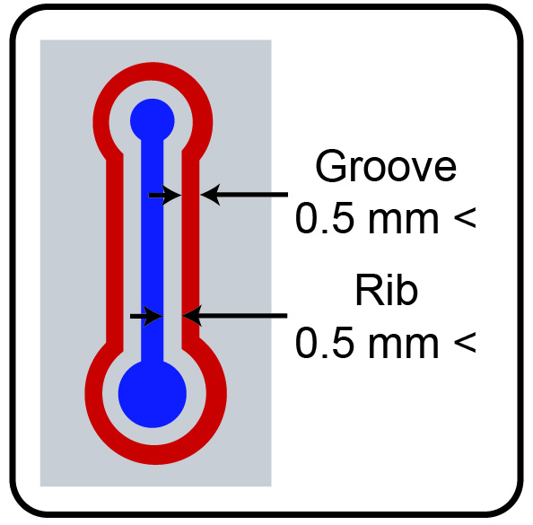
- Mill the designed structure in the aluminum sheet with the 0.25 mm end-mill.
3. Cleaning the aluminum substrate from residues. Dust is removed first with water, and then the surface is cleaned first with ethanol, and then with compressed air. Finally the substrate is dried in an oven (120ᴼC, 30 min).
4. Plasma activation of the quartz microscope slide. Place the quartz microscope slide inside the Plasma Cleaner. The plasma treatment is a ‘surface process’, therefore the surface that is about to be bonded should be facing towards the center of the chamber.
- Evacuate the chamber until a working pressure of 500 mTorr at a constant inflow of air is established.
- Switch the plasma on at 27 W, which is the highest intensity available for the specified Plasma Cleaner.
- ‘Turn off’ the plasma after 90 seconds.
- Vent the chamber of the Plasma Cleaner by opening the needle valve and allowing air to enter through the flow meter.
- Remove the activated piece of substrate from the Plasma Cleaner.
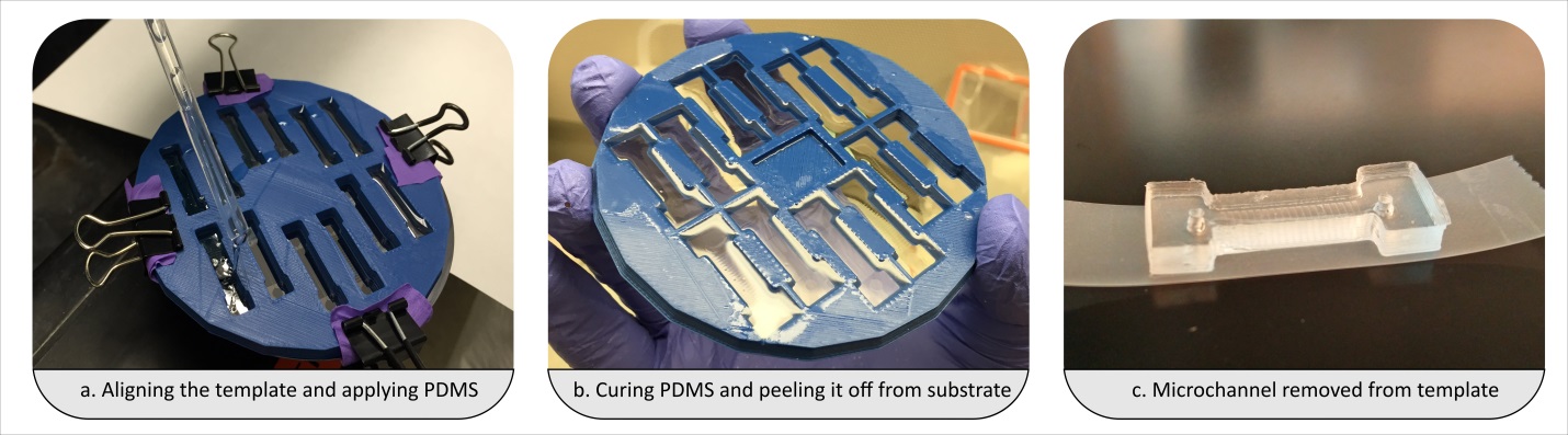
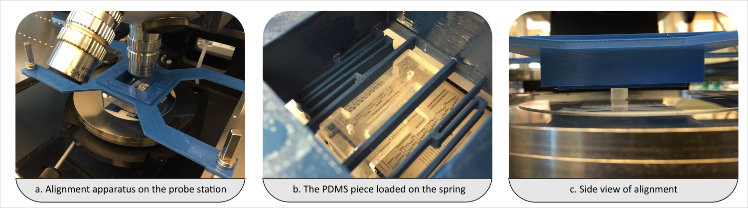
5. Bonding
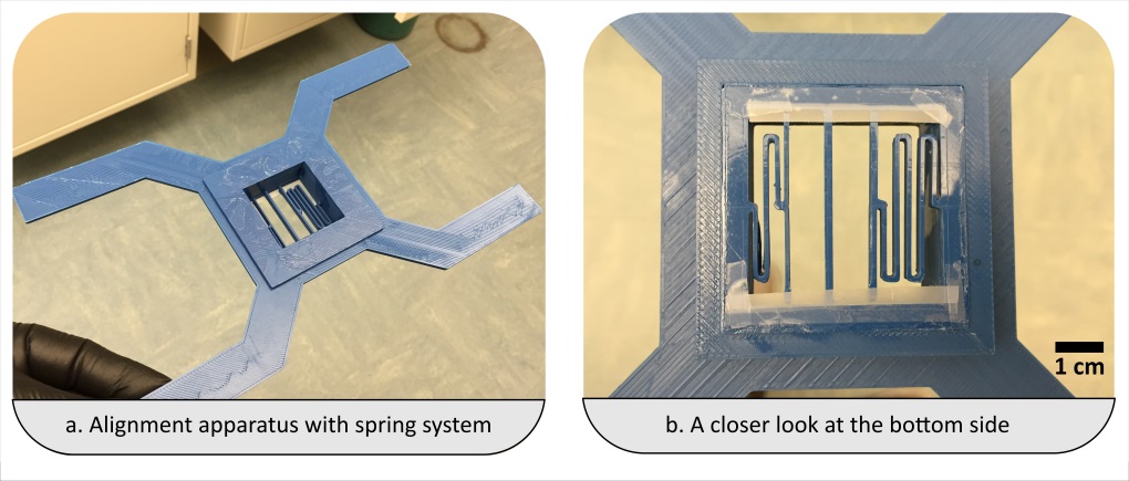
- Align the substrates (and thus enclose the micro fabricated structures) by firmly pressing the activated quartz surface to the aluminum sheet. A fine interfacial gap is forming between the quartz and aluminum surfaces.
- In case you have a large chip or thin fragile substrates you may need to carefully clamp the substrates together.
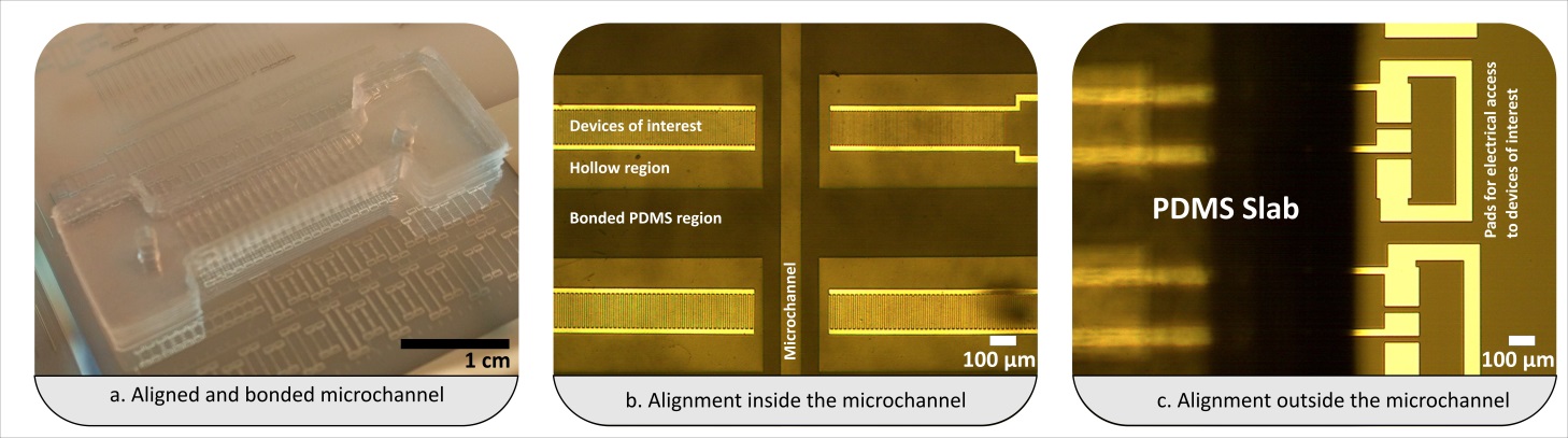
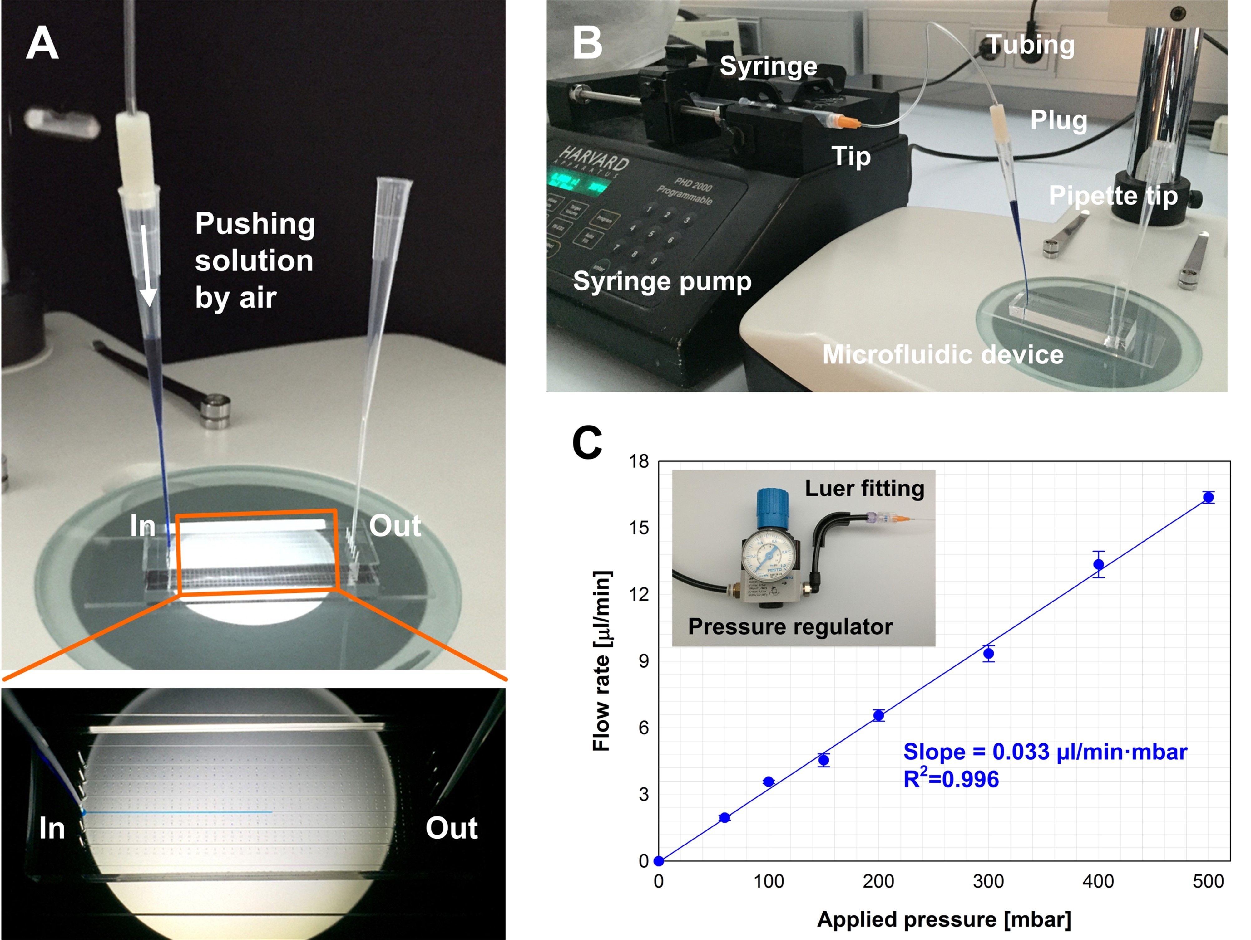
- Prime the gap with the adhesive while holding the two substrates of your device together. In order to do so, place a small drop of adhesive to one edge, i.e. to the gap between the two substrates. The adhesive will flow into the gap due to capillary action. Thick substrates will be held together sufficiently by the adhesive film. The flow of the adhesive will stop at the edge of the microfabricated structures as a results of surface effects (surface tension and wetting angle). Inspect whether the device is completely filled with the adhesive. Add more of the adhesive if necessary.
- Cure the completely primed device by exposing it to UV-light, 365nm @ 100 W for 5 to 10 minutes.
- Place the device into the oven at 50°C. According to the supplier’s specifications, the bond reaches its maximum strength after 12 hours at 50°C. Alternatively, for temperature-sensitive materials, longer incubation times at room temperature are also feasible.
The main advantages of the presented bonding method are as follows:
1. Hybrid microfluidic devices can be easily bonded.
2. The method is relatively simple and does not require clean-room conditions.
3. The method works with any UV transparent material as long as the surfaces are clean, smooth and as long as they can promote the capillary action necessary for the priming with adhesive.
4. It is an economic bonding method. An expected 30 mL of UV-curing adhesive should be enough for the bonding of over hundred microfluidic devices. Each assembly will thus cost less than £0.2 GBP (or approximately $0.3 USD).
What else should I know?
Q1. What processes do you use to create the holes in the quartz slide?
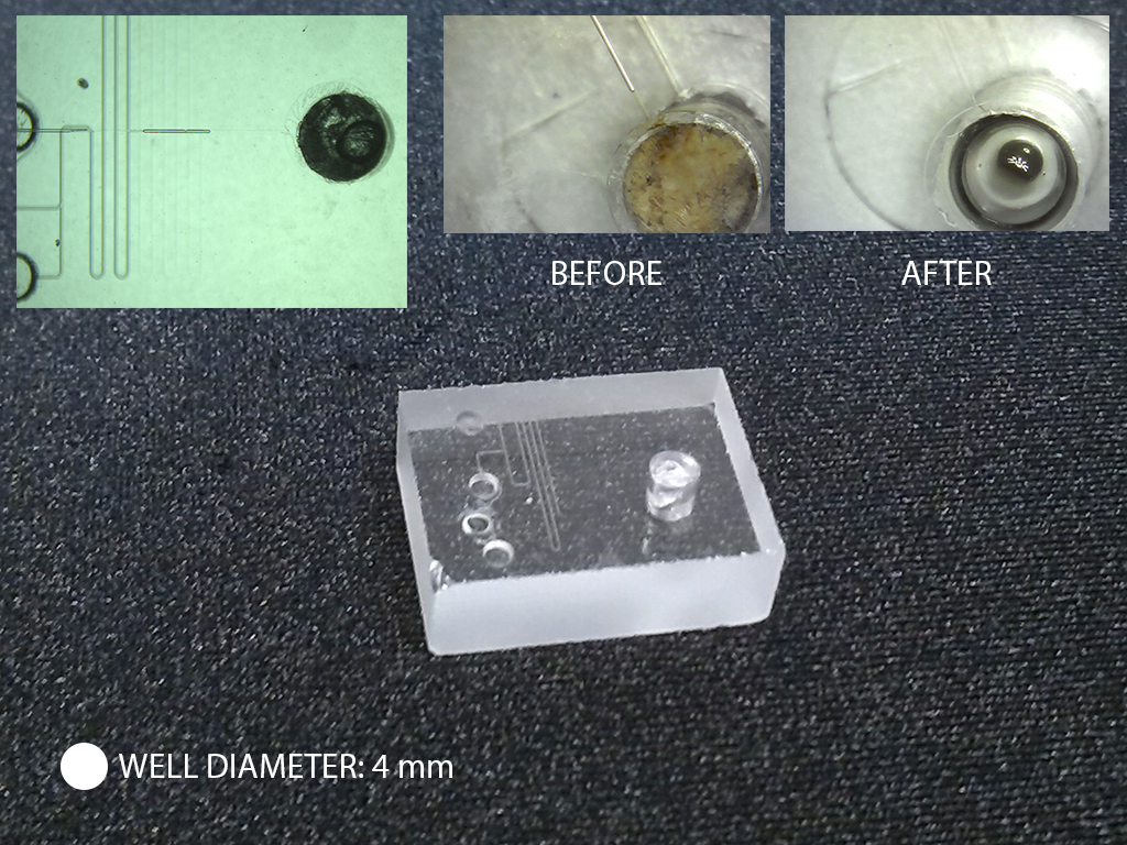
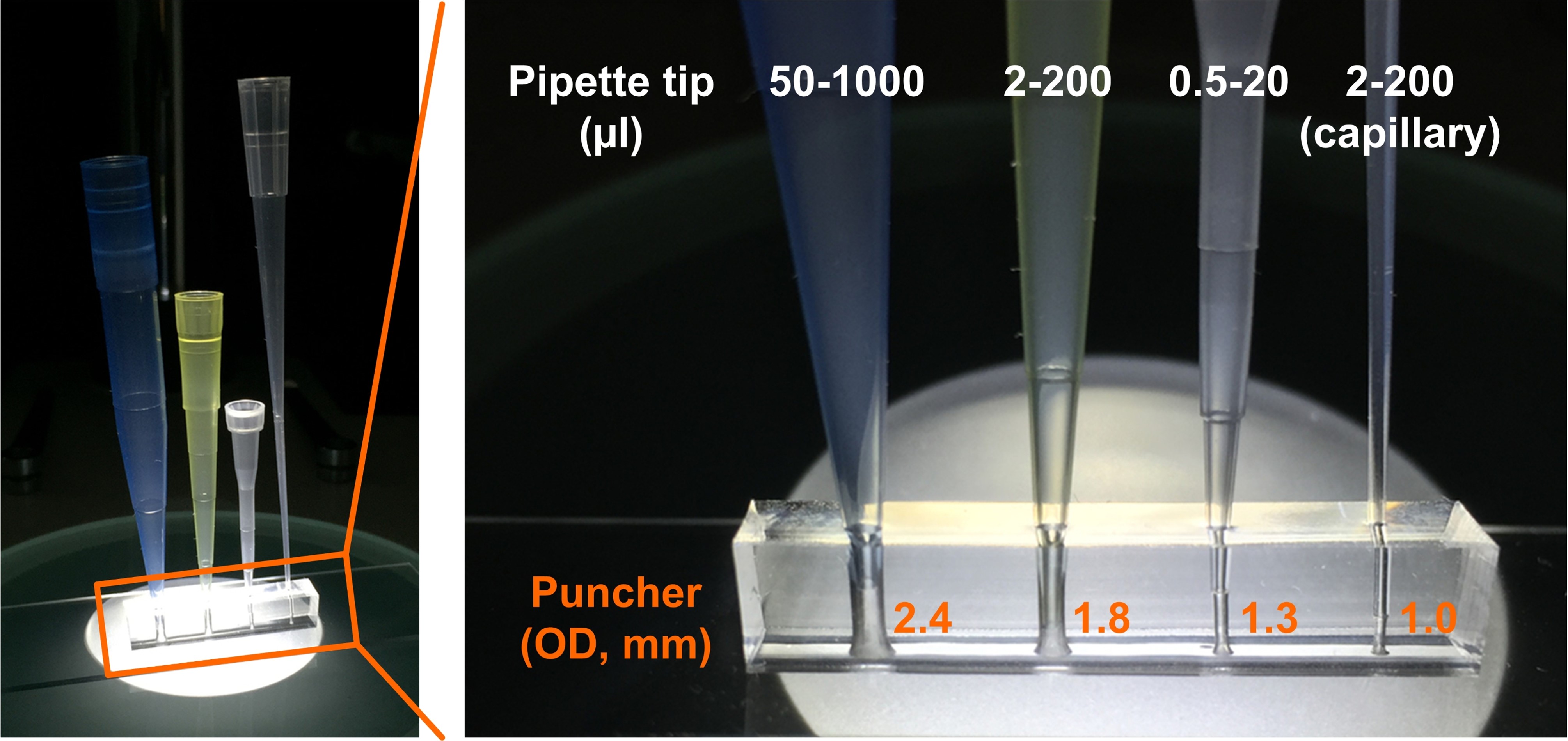
A1. The quartz slides are drilled with diamond drill bit (Eternal tools, UK), 1 mm in diameter, and a bench drill (D-54518, Proxxon , Germany) at 1080 rpm. This is a slow operation as the process is closer to grinding rather than drilling. To avoid crack formations in the quartz slide and to cool diamond bit a droplet of water is applied on the surface of the quartz. After each cycle grinded quartz debris may be accumulating at the bottom of the hole; it can be removed by using a pipette and cooling liquid.
Q2. Have you ever tried this method with channel geometries that are disconnected? For example, a channel layout shaped like an “O” that would prevent adhesive wetting from the edge of the slide?
A2. We had bonded successfully channels with complex, serpent geometries. For “O”-shaped channels we use additional feed, a hole, drilled in one of the substrates that allows the adhesive to spread.
Q3. Does the adhesive ever “burst” and enter the channels? If so, what methods do you use to minimize the chances of this happening?
A3. Yes, it happens occasionally that the adhesive fills the channel.
To prevent this: minimum amount of glue is applied at a time, and also the propagation of the front needs to be monitored. We wait until the glue reaches the channel edge, and then we place the assembly under the UV-light for curing.
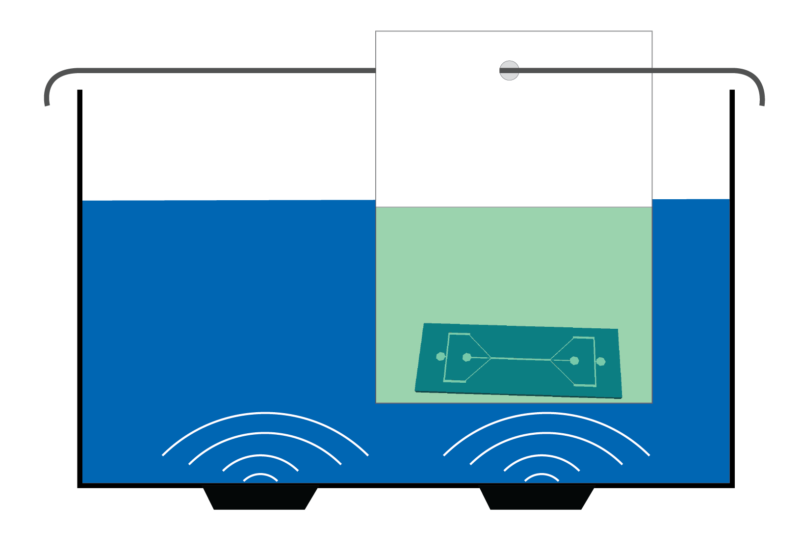
If the channel is filled with small amount of adhesive, the glue could be washed out with a bit of ethanol or acetone.
Completely filled channel requires disassembly, cleaning with acetone or ethanol of the substrates. Afterwards, the procedure can be repeated with less glue.


")


