Why is this useful?
Most of microfluidic devices use channels with rectangular cross-sections. The microfabrication of rectangular shaped channels is straightforward with standard tools such as photolithography.
Fluid dynamics, rheology, soft matter and, recently, biology-based investigations need circular cross-section microchannels; indeed, pre-fabricated capillaries are normally used to carry out the studies. However, capillaries are impractical for some investigations requiring complicated designs.
For Plexiglas® (or other plastic) devices, microfabrication by micromilling is a low cost procedure, which, in the last decades, has gained popularity in the field of microfluidic applications.1-2 The fabrication and the sealing of Plexiglas® microchannels with circular cross-section can be challenging.
Here, a method of fabrication of plastic microfluidic devices with circular cross-section is presented. The method is low cost and it can be performed by minimally trained users. The alignment step builds on a procedure first introduced by Lu et al. that used circular magnets to align layers of polydimethylsiloxane (PDMS).3 The protocol is validated for circular cross-section channels, but it can be used for fabricating rectangular channels or special inlets as well.
What do I need?
- Plexiglas® sheets (thickness 1mm) Rohm Italy
- CNC MicroMill (Minitech, US)
- Ball nose end-mills (0.001 inch, PMT Endmill)
- Magnets 4 mm × 4 mm× 4 mm, DX
- Microscope Bresser 58-02520
- Clamps RS Italy
- Ethanol
- Microscope (or stereomicroscope)
- Glass slides for microscopy (50 mm × 75 mm)
What do I do?
1. Computer aided design of the device (CAD).
- Design the microfluidic channels with CAD software. Fig. 1a displays the top and bottom layer of the main channel and, in particular, aligned square through-holes in each layer.
- Translate the CAD file to Computer Numerical Control (CNC) code for micromilling.
2. Micromilling
- The endmill should be aligned to set the point z=0 by using a microscope.
- Then, the microchannels (top and bottom) must be milled. Channel with depends on the endmill diameter.4 It is worth emphasizing that setting the correct work parameters (such as tool speed and depth) is crucial. Indeed, if the latter are not appropriate, the plastic workpiece develops internal stresses that during the bonding result in cracks and chip breakdown.
- Finally, the through holes and the frame have to be milled. The number of through holes for locating the magnets depends on the dimension of the microfluidic device. It is good practice for the rectangular through-holes to have a pitch of roughly 10 mm (this dimension depends on the size of the microchannels and of the magnets).
3. Alignment
- Align the top and bottom layers with a stereomicroscope (Fig. 1b). The bottom layer should be set on a solid surface and the magnets inserted into the through-holes. Then, the second layer should be placed on the first and a second set of magnets inserted in the square through-holes of the second layer.
- The magnets located in the first and second layer naturally provide a good “first alignment” of the microchannels, while leaving freedom to slightly adjust the layers (i.e., this is a reversible sealing). Once the magnets are fixed, the quality of the alignment should be checked with a microscope.
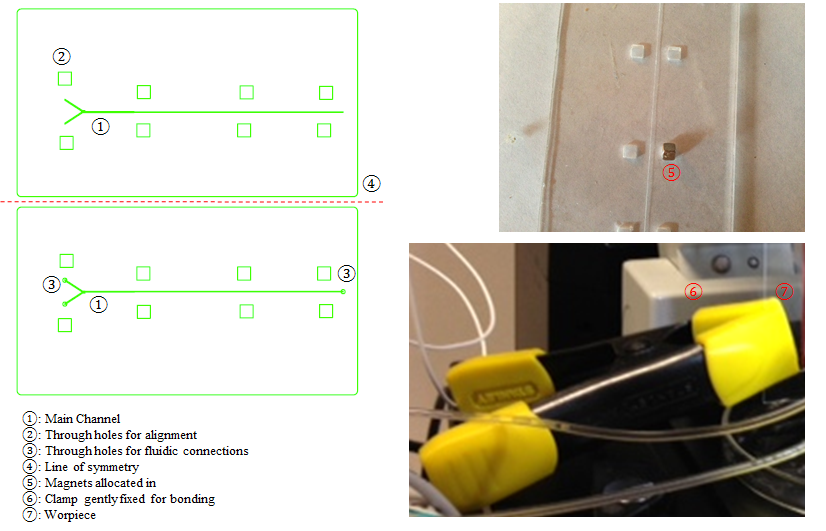
Fig. 1. The Fabrication. a. CAD design of a microfluidic channel with circular cross section. The length of the microfluidic device is 40mm, the width is 15mm. The depth of grooves is 50μm, width 25μm. b. Magnets employed for the bonding. C. Clamps used for sealing the microchannel.
4. Bonding
- Clamp the Plexiglas® layers together and submerge assembly in ethanol for 15 minutes (Fig. 1c). For optimal bonding, the clamping should be done with clamps positioned at the edges of the Plexiglas®.5
- After 15 minutes, the sealing of the microfluidic channels should be checked. If the Plexiglas® is sufficiently bonded, the magnets can be removed and glass slides placed on either side of the Plexiglas® layers. Clamp the glass slides and allow the assembly to rest for another 5-15 minutes.
- The device is ready to be used for different applications as shown in Fig. 2a. Capillary tubing can be easily connected to the channel for modular design (Fig. 2b).
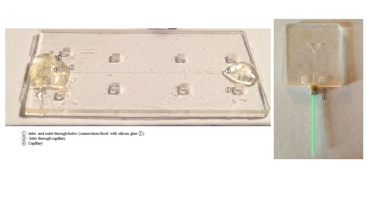
Fig. 2. Examples of microfluidic devices. a. Perfusion of the samples through hole at the inlet. b. Perfusion through capillaries.
In conclusion, analyzing the protocol, the following advantages can be emphasized:
- The process is designed for different materials, but it fits perfectly with Plexiglas®
- The equipment necessary for the fabrication and assembly includes simply a micromilling machine and a (stereo)microscope
- The use of square magnets (instead of circular ones) allows for more precise alignment due to further restriction to the sliding of the top and bottom layers.
References
- G. Simone, G. Perozziello, J. Nanosc. Nanotech., 2010, 11, 2057.
- G. Simone, RSC Advances, 2015, 5, 56848.
- J-C Lu, W-H Liao, Y-C Tung, J. Micromech. Microeng. 2012, 22, 075006-075014.
- G. Perozziello, G. Simone, P. Candeloro, F. Gentile, et al. Micro and Nanosystems, 2010, 2, 227-238.
- G. Medoro, G. Perozziello, A. Calanca, G. Simone, N. Manaresi, 2010, US Patent App. 13/257,545.


")