Author Archive

Electric drill/driver as centrifuge with 3D-printed custom holders for non-conventional containers

Minkyu Kima, Guanya Shib, Ming Panc, Lucas R. Blaucha, and Sindy K.Y. Tanga*

aDepartment of Mechanical Engineering, Stanford University, Stanford, CA 94305, USA

bUndergradute Visiting Research Program, School of Engineering, Stanford University, Stanford, CA 94305, USA

cDepartment of Materials Science and Engineering, Stanford University, Stanford, CA 94305, USA

*sindy@stanford.edu


Why Is This Useful?

Many processes in biological and chemical preparation require centrifugation steps. The transfer of samples between the original sample container and tubes required by commercial centrifuges increases the risk of sample contamination, and often leads to the loss of samples. Commercial centrifuges are also not readily available outside laboratory settings. Here we show the design of a simple 3D-printed holder for attaching to the chuck of an electric drill/driver which we use as a centrifuge. The advantages of this method include: 1) The holder can be designed to hold non-conventional containers (e.g., syringes, glass vials, capillaries). 2) Electric drill/drivers are more widely available than centrifuges. We show that a variety of samples (e.g., water-in-oil emulsions, cell suspensions, food and drinks, wet soil) in various containers can be centrifuged with our method. This method should be useful for field work outside of the laboratory, and for the wider DIY community interested in home-based applications that require centrifugation, such as blood separation and related diagnostics, separation of interstitial water from wet soil for pollution detection, extraction and identification of allergens in food samples, and fluid clarification (e.g., olive oil, wine) by accelerating sedimentation.

What do I need?

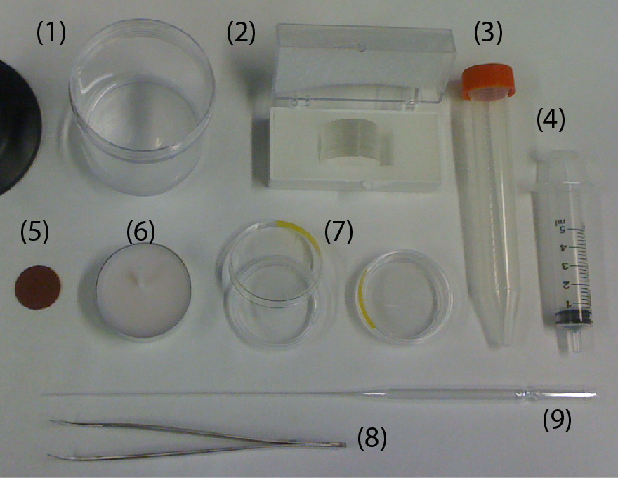
Figure 1. Photo of components needed.

  1. Electric drill/driver (DeWalt DC742KA Cordless Compact Drill/Driver Kit [1]).
  2. 3D-printed custom holder.
  3. 3D-printed custom support for the drill/driver.
  4. Four 1 mL-syringes (NORM-JECT, Part No.: 4010-200V0) as an example of non-conventional sample containers.
  5. One long bolt (Pan Head Machine Screw, Zinc, #8 x 1-1/4”) and one matching nut (Hex Nut, Zinc, #8-32). The dimensions of the bolt should match the chuck of the drill/driver.
  6. Four short bolts (Pan Head Machine Screw, Zinc, #6 x 1/2”) to secure the 1 mL-syringes to the 3D-printed custom holder.

What do I do?

  1. Design a custom holder using Solidworks or other CAD software.
    1. Measure the outer diameter (w1 = 6.5 mm) of the 1 mL-syringe (Fig. 2a). We included a 0.5 mm-tolerance in deciding the width of the slot (w2 = 7 mm) into which the 1 mL-syringe will be secured (Fig. 2b).
    2. Decide the angle (q = 60°) at which the 1 mL-syringe will be tilted relative to the plane of rotation.
    3. Decide the length (w3 = 80 mm) and the thickness (w4 = 15 mm) of the holder.
    4. Measure or identify the outer diameters of the short and long bolts, and use these values for f3 and f5 respectively.
  2. Design a custom support for the drill/driver (Fig. 2c). The dimensions of this support are not critical so long as the drill/driver is stable and does not topple during operation.
  3. 3D-print the holder and the support. We used a 3D-printer by ROBO 3D [2]. The resolution of the 3D-printer in xyz direction is 100 mm. The material we used was polylactic acid (PLA).
  4. Assemble the centrifuge (Fig. 2d).
    1. Put one long bolt through the center of the holder and tighten with the nut.
    2. Insert the bolt into the chuck of the drill/driver and tighten the bolt by pushing the trigger of the drill/driver a few times.
    3. Make sure the bolt is fixed in the chuck and aligned to the drill/driver.
    4. Place the drill/driver in the 3D-printed support.
    5. Secure four 1 mL-syringes to the holder using the four short bolts.
  5. Start the centrifuge by pushing the trigger of the drill/driver for 5-10 minutes. The plane of rotation should be parallel to the floor.
  6. Unscrew the short bolts to remove the syringes.
  7. If desired, measure the rotational speed of the drill/driver before inserting the real samples. We used the SLO-MO mode in iPhone to calibrate the rotational speed of the drill/driver [3] (Fig. 2e).
  8. Results (Fig. 3).
    1. Water-in-oil emulsion: Micron-sized uniform water-in-oil droplets were collected in a 1 mL-syringe. After a needle was connected to the syringe, the syringe was secured to the 3D-printed holder with needle pointing up. The holder was balanced before centrifugation by adding another syringe containing an equal weight of fluids to the opposite side of the holder. We centrifuged the sample at a speed of 374 rpm for 10 minutes. Droplets were then injected into a microchannel to measure the change of volume fraction before and after centrifugation. The volume fraction was defined as the ratio of the total volume of water droplets to the total volume of fluids filling up the channel. After centrifugation, the volume fraction of the emulsion increased from 60% to 86% without a change in the size of the droplets. Neither break-up nor coalescence of the droplets was observed.
    2. Stentor coeruleus: To demonstrate the concentration of cell suspensions, we used Stentor coeruleus (www.carolina.com) as a model. We filled a 3 mL-syringe with about 20 Stentor cells suspended in 2 mL of aqueous culture media (concentration ~ 10 cells/mL). A needle was connected to the syringe which was then secured in the 3D-printed holder with the needle pointing down. The cell suspension was centrifuged at a speed of 374 rpm for 5 min. The cells were concentrated at the bottom, close to the entrance into the needle. It was then possible to inject this concentrated cell suspension through the needle into a polyethylene tubing. Fig. 2-i) shows the microscopic image of the cells in about 15 mL of aqueous culture media in the tubing (concentration ~ 400 cells/mL).
    3. Korean rice wine (Makgeolli): A separate holder was designed to hold a 20 mL-glass vial. The vial was filled with 12 mL of Korean rice wine and centrifuged at a speed of 1252 rpm for 10 minutes. The sediment was clearly observed after centrifugation. On the other hand, the sediment was not observed for more than 20 minutes without centrifugation.
    4. Wet soil: 10 mL of wet soil in a 20 mL-glass vial was centrifuged at a speed of 1252 rpm for 10 minutes. Interstitial water was separated from the soil.

Figure 2. a) A 1-mL syringe as non-conventional container. b) Drawing of 3D-printed holder generated by SolidWorks. c) Drawing of 3D-printed support generated by SolidWorks. d) Photograph of experimental setup. The 3D-printed holder was connected to the drill/driver placed on the 3D-printed support. Four 1 mL-syringes were then tightened using the short bolts. e) Calibration plot of the rotational speed versus the trigger levels on different modes of the drill/driver. Mode 1 and Mode 2 indicate different gear settings in the transmission of the drill/driver. The numbers 1 to 3 in each mode indicate user-defined trigger levels. The rotational speed ranges from 120 rpm to 1252 rpm. The rotational speeds were measured using SLO-MO function in iPhone 6.

Figure 3. a) Photographs of emulsion in 1 mL-syringe and microscopic images of emulsion injected into a microchannel before and after centrifugation. The scale bar in the photographs is 5 mm. b) Photographs of Stentor cells in 3 mL-syringe before and after centrifugation. The red arrows indicate individual cells. The scale bar is 5 mm. i) Microscopic image of 6 Stentor cells in a polyethylene tubing after centrifugation. The scale bar is 300 mm. c) Photographs of Korean rice wine in 20 mL-glass vial before and after centrifugation. The red box indicates sediments. The scale bar is 10 mm. d) Photographs of wet soil in 20 mL-glass vial before and after centrifugation. The red box shows interstitial water separated from wet soil. The scale bar is 10 mm.


What else should i know?

  1. The centrifugal force can be increased by lengthening the arms (w3) holding the containers.
  2. The rotational speed can be measured using a high-speed camera or a smart phone with slow-motion videotaping capability, so long the frame rate is sufficient for the rotational speed used.
  3. The load in the centrifuge should be balanced.
  4. For safety purposes, safety goggles should be worn. The centrifuge should also be placed inside a safety barrier (e.g., a sturdy laundry basket). The safety instructions for the drill/driver should also be observed.
  5. After centrifugation for 10 minutes, we found that the drill/driver started to heat up. If centrifugation time longer than 10 minutes is needed, it should be possible to perform multiple rounds of 10-min centrifugation steps with breaks in between to cool down the drill/driver.

Conclusion
In this work, we demonstrated that 3D-printed holders attached to an electric drill/driver can be used for the centrifugation of samples in non-conventional containers. As 3D-printers and hand drills are easily accessible, we expect this tip to find immediate use in settings outside laboratories for field work, and also at home for DIY users.

    Acknowledgements

    We acknowledge support from the Stanford Woods Institute for the Environment and the National Science Foundation (Award #1454542 and #1517089).

    References

    1. http://www.dewalt.com/products/power-tools/drills/drills-and-hammer-drills/12v–38-10mm-cordless-compact-drilldriver-kit/dc742ka

    2. http://store.robo3d.com/collections/all/products/r1-plus-3d-printer?variant=6274616835

    3. http://www.imore.com/how-to-record-video-iphone-ipad


Digg This
Reddit This
Stumble Now!
Share on Facebook
Bookmark this on Delicious
Share on LinkedIn
Bookmark this on Technorati
Post on Twitter
Google Buzz (aka. Google Reader)

Low Temperature Melting Metal Solders For Electrical Interconnects On Plastics

Abdul Wasay, Dan Sameoto
Department of Mechanical Engineering, University of Alberta, Edmonton, T6G 2R3, CANADA.
Email: sameoto@ualberta.ca

Why is it useful?

Electrodes have been used for driving electrochemical reaction on various Lab on chip applications, running electroosmotic pumping or simple sensing of current or voltages. With the recent thrust to move to thermoplastics, simple electrodes have been patterned at low temperatures using vacuum plasma sputtering via intermediate masks1 or ink electrodes2. While, wire-bonding or soldering have been the standard protocols for providing interconnections to the bond pads on silicon or glass chips, the temperatures in these cases are often beyond the glass transition or even melting temperatures of most thermoplastic substrates, which leads to defects and ineffective connection. Other techniques such as conductive epoxies can be problematic due to longer cure times, permanent fixtures and potentially low uniformity of conductive properties which are affected by sintering times and temperatures.

We present a simple soldering technique using low temperature melting metals that is compatible with nearly any thermoplastic substrate and thin-film electrodes.

Fig.1. Basic Apparatus

  • Field’s metal (eutectic alloy of 32.5% Bi, 51% In, 16.5% Sn) preferred for low toxicity, although lead based alternatives exist.
  • Syringe connected to tygon tube
  • Copper wire
  • Aluminum foil dish
  • Electrodes patterned on thermoplastic substrate (here, polystyrene with  ~ 20 nm thick Au electrodes)

Tools

  • Hot Plate
  • Shearing scissor
  • Hot glue gun (in this case a Mastercraft dual temperature glue gun, operated at low temperature setting)

What do I do?

To extrude the Fields metal into a thin filament, (Fig.2)

  • melt the Fields metal (ROTO1443;  Tm=62.2oC, typical resistivity ~520nΩ-m) in an aluminum foil dish.  The metal is very soft, so bolt cutters can easily remove smaller portions for melting if desired.
  • use a suitable diameter and length  tygon tube and pull the molten metal into it using a syringe – it will freeze within a few inches (1/32” inner diameter tube shown here).
  • allow it to cool to room temperature (less than a minute) and then pull out the filament.

Soldering Process,(Fig.3.)

  • Hold the Field’s metal filament with a hot glue gun used for lower melting point glues (measured tip temperature   ̴120 C) over the electrode patterned petri dish and melt it over the electrodes.
  • Solder the copper wire with the Field’s metal.  After soldering, excess metal can be removed from the hot glue gun tip with paper towel.

The resultant solder is strong enough to be used for mainstream lab on chip applications. They can be removed by a strong tug, under which case the thin electrodes on plastics could be stripped.

Fig.2. Fields metal extrusion process

Fig.3. Soldering process

Fig.4. Gecko adhesives based reversibly bonded4 capillary electrophoresis device with integrated electrodes

Fig.5. a) Demonstration of solder strength b) small electrode stripping as observed when the solder is removed by a strong tug

What else should I know?

While there are quite a few options of low melting temperature metals to choose from, most of them contain heavy metal like lead or cadmium, which may ideally be avoided. While Field’s metal is relatively expensive due to the indium content, the solders can be recovered for reuse in the lab and in general is a better option for electrically connecting thin-film electrodes to temperature sensitive substrates in a quick, reliable fashion.

Watch the video here: Low Temperature Melting Metal Solders For Electrical Interconnects On Plastics

References:

1 A. Toossi, M.Sc, University of Alberta, 2012.
2 C. E. Walker, Z. Xia, Z. S. Foster, B. J. Lutz and Z. H. Fan, ELECTROANALYSIS, 2008, 20, 663-670.
3 http://www.rotometals.com/product-p/lowmeltingpoint144.htm
4 A. Wasay and D. Sameoto, Lab Chip, 2015, (DOI:10.1039/C5LC00342C).

Digg This
Reddit This
Stumble Now!
Share on Facebook
Bookmark this on Delicious
Share on LinkedIn
Bookmark this on Technorati
Post on Twitter
Google Buzz (aka. Google Reader)

The use of polymer filaments or metal wires to pattern arbitrary-shaped micro-sized electrodes for microfluidic applications

Bruno Rafael Becker1, 2, Tristan Sun1, Shengjie Zhai1 and Hui Zhao1

1. Department of Mechanical Engineering, University of Nevada, Las Vegas NV, US

2. Department of Mechanical Engineering, Universidade Tecnologica Federal do Parana, Brazil

Why is this useful?


Electric fields are widely used to manipulate particles or fluid in lab-on-a-chip systems, for example to separate or assemble particles and pump or mix liquids, due to their favorable scaling with miniaturization. In order to exploit the advantages of electric fields, electrodes have to be fabricated and integrated with lab-on-a-chip devices. Patterned electrodes can also serve as biosensing by measuring the electric current change due to biomolecular binding. Traditional lithography has been used for such electrode fabrication, but particularly for arbitrary shaped electrodes, it is time consuming, requires expensive equipment and needs to be conducted in a cleanroom environment.

Hence, here we developed a simple fabrication method using commercial polymer fishing lines or metal bonding wires as a mask that does not require sophisticated procedures, expensive specialized instruments, and can be done outside a cleanroom environment. The gap size between the electrodes can be controlled by the commercial polymer fishing lines or metal bonding wires (from 1 mm to 1 mm). Due to the flexibility of fishing lines or metal wires, electrodes with arbitrary shapes can be readily fabricated by manipulating flexible lines. The fabrication method is particularly useful for demonstration of proof-of-concept or quick prototyping in terms of searching for the optimal shape, or researchers who lack the access to cleanroom or expensive lithographic equipment.

What do I need?


  • Glass slides
  • 3M double-sided tape
  • Deionized water (DI water)
  • Isopropyl alcohol
  • Acetone
  • Ultrasonic cleaner
  • Plasma cleaner
  • Sputter coating machine
  • Commercial fishing lines or metal bonding wires

What do I do?


1. Use DI water to clean the glass slide in the ultrasonic cleaner for 240 seconds and then dry the slide with the pressurized air (Fig. 1).


Fig 1. Using the ultrasonic cleaner to clean the glass slide.

2. Repeat the step 1 with isopropyl alcohol.

3. Repeat the step 1 with acetone. Acetone not only dissolves remaining contaminants but also provides negative surface charges to the glass surface to prevent adhesion of colloidal particles.

4. Put the glass slide into the oxygen plasma cleaner for 2 minutes (Fig. 2).

Fig 2. Using the plasma cleaner to clean the glass slide.

5. Use the double-sided tape to fix the fishing line on the glass slide.

6. Cover the glass slide with a cut paper. The cut paper along with the fishing line serves as a mask. The double-sided tape also keeps the paper fixed on the glass slide (Fig. 3).

Fig 3. The fishing line along with the cut paper serves as the mask.


7. Place the glass slide covered with the mask in the sputter coating machine (Fig. 4).

Fig 4. Put the glass slide into the sputter coating machine.

8. Sputter coating for 50-60 seconds to get 50-60 nm thickness metal electrodes.

9. Remove the mask from the glass slide (Fig. 5).

Fig 5. Patterned electrodes with the fishing line ready for use.

What else should I know?


Copper wires with a diameter of 140 µm were also tested. But because of their rigidity, they could not be aligned securely with the glass surface; consequently, the gold was sputtered around the wire and contaminated the channel. A 25 µm gold bonding wire was tested to determine the applicability of the method to fabrication with even smaller feature sizes. Electrodes with a 25 µm gap size are successfully fabricated, showing the robustness of our method (Fig. 6).


Fig 6. Patterned electrodes with the 25 µm gold bonding wire.

In the end, we connected the electrodes with a 100 ohms resistor with the electrodes, applied a voltage, measured the current, and plotted the I-V curve (Fig. 7). The I-V curve shows that the resistance of the electrodes is around 10 ohms, demonstrating the effectiveness of our method in patterning electrodes.

Fig7. Measured currents as a function of the applied voltages.

Experiments with the fabricated gold electrodes


We used the fabricated electrodes to assemble colloidal particles into functional structures (Fig. 8). Due to the dipole-dipole interactions induced by the applied electric fields, 5 micrometer latex particles are assembled into ordered structures with an AC electric field of 100 KHz and 10 V, which can find applications in photonics or biosensing.


Fig.8 Assembly of 5 m colloidal particles using the electric field.

Digg This
Reddit This
Stumble Now!
Share on Facebook
Bookmark this on Delicious
Share on LinkedIn
Bookmark this on Technorati
Post on Twitter
Google Buzz (aka. Google Reader)

Different strategies for the fabrication of cell culture chambers for live-cell imaging studies

David Caballero1,2, Josep Samitier1,2

1 Nanobioengineering group, Institute for Bioengineering of Catalonia (IBEC), Barcelona, Spain

2 Centro de Investigación Biomédica en Red de Bioingeniería, Biomateriales y Nanomedicina (CIBER-BBN), Zaragoza, Spain.

Why is this useful?


Long-term imaging of cells is typically performed using standard Petri dishes. Frequently, these ´chambers´ are not convenient when sample manipulation and treatment (e.g. functionalization, immunostaining…) is needed, both before and after the experiment1. To overcome this ´problem´, glass coverslips are used. They can be easily manipulated when following multistep protocols prior to cell deposition. For live-cell microscope imaging, the customized coverslips are secured into holders (chambers) containing the adequate cell culture medium2, 3. These holders are either supplied by the microscope manufacturers or fabricated in a mechanical workshop; this implies time for the design and money.

In this work we show two different strategies for the simple, fast and cheap fabrication of chambers for live-cell imaging, using materials and simple tools typically available in a bioengineering laboratory. These materials include Petri dishes, polydymethylsiloxane (PDMS), Falcon tube cap and glass coverslips. In the first strategy (A) we drill a hole in a Petri dish where a customized glass coverslip is adhered at the bottom using wax. In the second strategy (B), a PDMS frame is used to hold the coverslip inside a Petri dish. Depending on the user final application one strategy is recommended over the other (see below). All the material is biocompatible and simple to obtain. These two methods provide several advantages: (i) they are easy and cheap; (ii) the chambers can be fabricated in a short-time period; (iii) this approach avoids the purchase of commercially-available holders or ordering the fabrication to a mechanical workshop.

What do I need?


    Figure 1

Figure 1. Material needed for the fabrication of the home-made chambers.

(1) PDMS
(2) Glass coverslip #1, 25 mm in diameter
(3) Cap of a 15 mL Falcon (any brand)
(4) Syringe 5mL
(5) Polishing paper
(6) Wax
(7) P35 plastic Petri dish (any brand)
(8) Sharp Tweezers
(9)Glass Pasteur pipette

You will also need:

  • Hot plate
  • Bunsen burner (optional)
  • Soldering iron (or drill)
  • EtOH 70%
  • Oven
  • SYLGARD 184 PDMS and crosslinker agent (Dow Corning)


What do I do?


Figure 1 (above) shows all the material needed for the fabrication of the home-made chambers using both strategies A and B. The steps describing both strategies are detailed next.

STRATEGY A:

1. Make a circular hole of around 2 cm in diameter in the middle of the lower part of a P35 Petri dish using a pre-heated, sharp-tip soldering iron. Alternatively, a drill can be used. Ensure a perfect circular hole by using a 15 mL Falcon cap as a template (see Fig.2a-c).

Figure 2. Fabrication of the cell culture chamber using Strategy A. Drilling a hole on the lower part of a Petri. (a) First, draw a circumference of about 2 cm in diameter in the center of the lower part of a Petri dish. Use a 15 mL Falcon cap as template. (b-c) Next, a soldering iron is used to drill a hole. (d) Finally, the edge of the hole is polished using thin polishing paper.

2. Polish the hole using polishing paper (see Fig.2d). Check that the Petri is free of debris. Rinse the sample with etOH 70%. (Optional: Sonicate).

3. Use the tweezers to place and secure the glass coverslip on the back side of the holey dish with its customized side (e.g. functionalized) facing the inner part of the Petri (see Fig.3a-b).

Figure 3. Adhering the glass coverslip to the lower part of the drilled Petri dish using wax. (a) The drilled Petri dish and glass coverslip #1, 25 mm in diameter are (b) placed together and secured using the tweezers. (c) Next, the wax is melted using a heat plate. A small volume is absorbed by capillarity using a glass Pasteur pipette. (d) Following the edge defined by the coverslip and the dish, the chamber is sealed. This step is critical to ensure a good sealing. (e) Check that no open remaining points are left. (f) A Bunsen burner or equivalent can be used to melt the solidified wax inside the pipette.

4. Melt the wax using the hot plate and fill the Pasteur pipette with a small volume (see Fig.3c). NOTE: Capillarity will make the liquid wax to flow inside the pipette.

5. Gently, put in contact the tip of the pipette (filled with wax) with the coverslip. Follow the edge formed by the coverslip and the Petri (see Fig.3d). Cover it completely with wax until the entire contour is sealed (see Fig.3e). Refill the pipette if necessary. NOTE 1: The wax may solidify inside the pipette quickly. If so, melt it again using the Bunsen burner (or equivalent) (see Fig.3f). NOTE 2: Ensure that no empty spaces are left; cell medium will flow through them.

6. Culture the cells of interest (see Fig.4). Place the chamber inside the microscope and start the live-cell imaging experiment. NOTE: Manipulate gently the sample.

Figure 4. Finished chamber for live-cell imaging experiments. (a) Front view of the chamber filled with cell culture medium. (b) Back side view showing the wax-sealed region. No leakage is observed. The coverslip can be easily recovered after the experiment by pushing it down gently with the tweezers.

7. At the end of the experiment, the medium can be removed and the coverslip detached by pushing it down gently with the tweezers. Treat the sample as desired (e.g. immunostaining).

STRATEGY B:

1. Insert upside down the cap of a 15 mL Falcon in the middle of a P35 Petri dish (see Fig.5a).

Figure 5. Fabrication of the cell culture chamber using Strategy B. (a) A 15 mL Falcon cap is placed in the center of a P35 Petri dish. The empty region is filled with PDMS using a syringe. (b) The sample is degassed and cured. (c) The cap is removed and the PDMS frame released.

2. Fill the empty space with a syringe (or equivalent) with PDMS in a 10:1 ratio (pre-polymer:cross-linker). Degass and cure it at 65ºC for 4h (see Fig. 5b). NOTE 1: Holding the cap with adhesive tape will ensure that it remains in the center during curing. In this case, curing must be performed at RT overnight. NOTE 2: A very thin PDMS layer may appear after the removal of the cap. Remove it manually to ensure a through-hole in the PDMS. Alternatively, a weight can be applied on top of the cap.

3. Remove the cap using the tweezers and release the PDMS frame (see Fig. 5c).

4. Sterilize the PDMS frame. Rinse it with etOH 70% and UV-irradiate for 15 min.

5. Working in the cell culture room, deposit a drop (~50 uL) of culture medium in the center of a new P35 Petri dish (see Fig. 6a).

Figure 6. Finished chamber for live-cell imaging experiments. (a) A small drop of cell culture medium is deposited in the center of a new P35 Petri dish. (b) The customized coverslip is placed on top of it. (c) The PDMS frame is introduced inside the Petri and pushed down to hold the coverslip forming the chamber. Finally, the chamber is filled with cells.

6. Place the (customized) glass coverslip facing-up on top of the drop (see Fig. 6b). NOTE: This will ensure that no air bubbles are formed. Hold it with the PDMS frame.

7. Culture the cells of interest (see Fig. 6c). Place the sample inside the microscope and start the experiment.

8. At the end of the experiment, the medium can be removed and the coverslip released by removing the PDMS frame with the tweezers. Treat the sample as desired (e.g. immunostaining).

Figure 7. Microfabricated coverslips for live-cell imaging studies. (a) Glass coverslip covered with PDMS microstructures. (b) The modified coverslip can be used for the fabrication of chambers using both strategies. (c) Zoomed image of the microstructures (parallel grooves). The dimensions are: 1 um x 1 um x 1 cm (HxWxL); the separation between grooves is 1 um. Scale bar: 10 um. (d) NIH3T3 fibroblasts aligned parallel to the grooves. The arrow shows the direction of the structures. Scale bar: 50 um.


What else should I know?


By using these two approaches, chambers can be easily fabricated in the lab. Most importantly, this approach allows the manipulation of coverslips before and after the experiment with cells. If the coverslips are (bio)chemically modified (e.g. micropatterned with proteins of the extracellular matrix), manipulation must be performed carefully and fast to avoid sample degradation. Similarly, for cell guidance assays, coverslips can be easily modified with microfabricated structures to orient cell growth and motility (see Fig. 7), following the same steps described in this protocol.

For Strategy A, users must be aware of the melting temperature of wax (around 45ºC). This implies that the sealing may be fragile when performing the experiments at 37ºC and manipulation must be performed gently to avoid liquid leakage. Other materials and shapes, besides circular glass coverslips, could be used. This will depend on the experimental requirements of the user. For Strategy B, the PDMS frame and the coverslip could be used without the Petri in some applications. However, for live-cell imaging, a perfect fit between the chamber and the microscope stage is needed and the use of the Petri is therefore strongly recommended.

Finally, the user must consider the magnification needed for the experiment and the thickness of the sample on each strategy. Strategy A is recommended for high magnification microscopy (40X – 100X) and Strategy B for low magnification (4X – 20X). If needed, thinner coverslips (#0) could be used.


Acknowledgements

Dr. Daniel Riveline, Dr. Jordi Comelles (Laboratory of Cell Physics ISIS/IGBMC, Strasbourg, France) and David Izquierdo (Nanobioengineering group – IBEC, Barcelona, Spain) are acknowledged for technical help and discussions.

References

1.      Zanella F, Lorens JB, Link W. High content screening: seeing is believing. Trends Biotech 2010; 28:237-45.

2.      Caballero D, Voituriez R, Riveline D. Protrusion Fluctuations Direct Cell Motion. Biophysical Journal 2014; 107:34-42.

3.      Riveline D, Buguin A. Devices and methods for observing the cell division WO/2010/092116, 2009.

Digg This
Reddit This
Stumble Now!
Share on Facebook
Bookmark this on Delicious
Share on LinkedIn
Bookmark this on Technorati
Post on Twitter
Google Buzz (aka. Google Reader)

Reservoir Poly(dimethylsiloxane) Cap Fabrication

Luis G. Rigat-Brugarolas1,2, Antoni Homs-Corbera1,2 and Josep Samitier1,2,3

1 Nanobioengineering group, Institute for Bioengineering of Catalonia (IBEC), Barcelona, Spain
2 Centro de Investigación Biomédica en Red de Bioingeniería, Biomateriales y Nanomedicina (CIBER-BBN), Zaragoza, Spain.
3 Department of Electronics, Barcelona University (UB), Martí I Franques, 1, Barcelona, 08028, Spain.

Why is this useful?


Microfluidic devices are often connected to external reservoirs in order to perform experiments with large samples or to generate some types of closed loop systems.1 When containing biological content, once sealed and fluidically connected, these reservoirs should allow proper gas exchange and facilitate their placement in a controlled environment such as an incubator.2 On the other hand, often the connections used for this kind of assays may also suffer from sample leakages.

In this work we present a simple and cheap way of facing these issues by introducing a fabrication methodology for a sealing cap made of poly(dimethylsiloxane) (PDMS) that can be used for any kind of reservoir or bottle. The cap can be customized in order to allow multiple tubing connections depending on the specific user needs. PDMS is easy to manipulate, it’s biocompatible and permits gas exchange.3 This solution, consisting on fabricating a flexible PDMS cap covering the reservoir, should become a versatile alternative to expensive or unreliable other strategies and could be used in several microfluidic applications.

What do I need?


  • PDMS and crosslinker agent.
  • Plastic or glass reservoir.
  • Scalpel.
  • Tubing.
  • Oven.
  • Harris Uni-Core punchers or any kind of punchers.
  • Petri dishes.
  • Plasma cleaner.

What do I do?


Figure 1 shows the basic utensils and products needed to fabricate the PDMS cap.


Fig 1: Basic utensils and products needed to fabricate the PDMS cap

The steps are detailed next:

  1. Place reservoir/bottle in an upside down position inside a Petri dish. Fill the plate with PDMS as shown in Figure 2. In addition, fill another empty Petri dish with a thin layer of PDMS.
  2. Place both plates/samples inside an oven in a 65-90 ºC temperature range (depending on the reservoir’s material) for about 1.5 hours (Figure 3).
  3. Once the samples have polymerized, they have to be taken from the dishes (Figure 4), and the one corresponding to the reservoir cap replica can be cut, if needed, with a scalpel, as shown in Figure 5.
  4. After cleaning both samples with ethanol, they have to be chemically modified in O2 plasma (1 minute at high frequency, Figure 6) and immediately pressed together to form a permanent bond. It is important that the flat piece is sealed to the correct side of the cap replica.
  5. Once the final piece is achieved (Figure 7 left), it is useful to use Harris Uni-Core punchers in order to pierce the sample with the diameter of the tubing that is going to be used. It is recommended to make the holes with a slighter smaller diameter than the outer diameter of the tubing to form a pressure seal between the tubing and the hole (Figure 7 right); this will prevent leakage of the sample or undesired particles entering to the reservoir.
  6. Finally it is possible to screw the PDMS cap into the reservoir (an example is shown in Figure 8).

Fig 2: Fill two Petri dishes with PDMS, one with the reservoir (upside down) and the other just has to be covered with a thin polymer layer

Fig 3: Dispose the dishes inside an oven for 1-2 hours at 65-90ºC

Fig 4: An example of two PDMS samples. The left one corresponds to the reservoir cap replica. The right one to the PDMS thin layer

Fig 5: PDMS cap replica

Fig 6: Dispose both samples in a plasma cleaner in order to chemically modify the PDMS surfaces and join the cap with the PDMS plane piece

Fig 7: In order to pierce the access holes, a puncher is needed; afterwards the tubing can be connected to the PDMS cap

Fig 8: Example of a PDMS cap screwed into a plastic reservoir


References

[1] Herricks T., Seydel KB., Turner G., Molyneux M., Heyderman TT., Rathod PK.  (2011) A microfluidic system to study cytoadhesion of Plasmodium falciparum infected erythrocytes to primary brain microvascularendothelial cells. Lab Chip, 11, 2994.

[2] Rochow N., Manan A., Wi W., Fusch G., Monkman S., Leung J., Chan E., Nagpal D., Predescu D., Brash J., Selvaganapathy PR., Fusch C. (2014) An integrated array of microfluidic oxygenators as a neonatal lung assist device: in vitro characterization and in vivo demostration. Artif Organs, Doi: 10.1111/aor.12269.

[3] Regehr KJ., Domenech M., Koepsel JT., Carver KC., Ellison-Zelski SJ., Murphy WL., Schuler L., Alarid ET., Beebe DJ. (2009) Biomedical implications of polydimethylsiloxane-based microfluidic cell culture. Lab Chip, 9, 2132–2139.

Digg This
Reddit This
Stumble Now!
Share on Facebook
Bookmark this on Delicious
Share on LinkedIn
Bookmark this on Technorati
Post on Twitter
Google Buzz (aka. Google Reader)

Welcome to Chips & Tips

Welcome to Chips & Tips – a unique and regularly updated forum for scientists in the miniaturisation field from Lab on a ChipChips & Tips aims to provide a place where ideas and solutions can be exchanged on common practical problems encountered in the lab, which are seldom reported in the literature.

Do you

  • have problems with bubble formation when injecting your sample?
  • wish there was a quicker way to make prototypes?
  • find connecting chips to pumps and syringes problematic?

Or do you have your own tricks to overcome problems like these?

If so, then Chips & Tips is the forum to address your requirements!  Read the Tips below or see the author guidelines on how to submit your own today.

Chips & Tips is moderated by Glenn Walker (North Carolina State University).


Please note that Chips & Tips before April 2011 were originally published at www.rsc.org.

Digg This
Reddit This
Stumble Now!
Share on Facebook
Bookmark this on Delicious
Share on LinkedIn
Bookmark this on Technorati
Post on Twitter
Google Buzz (aka. Google Reader)