Jiaxing Wang1, Mingxin Zheng2, Wei Wang3,4*, and Zhihong Li3,4
1 Basic Medicine School, Peking University Health Science Center, Beijing, 100191, China
2 YuanPei College, Peking University, Beijing, 100871, China
3 Institute of Microelectronics, Peking University, Beijing, 100871, China
4 National Key Laboratory of Science and Technology on Micro/Nano Fabrication, Beijing, 100871, China
* E-mail: w.wang[at]pku.edu.cn
Why is this useful?
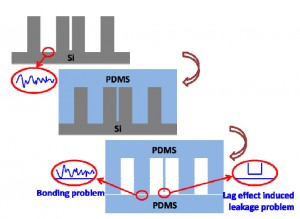
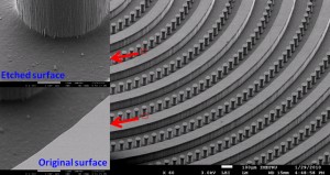
Nowadays, microfabricated silicon has been widely used as a master in PDMS-based soft lithography. It carries the merits of the microelectromechanical system (MEMS) technique, such as being able to construct complex 3D or high aspect ratio micro/nanostructures. However, the silicon master is easy to break during the PDMS moulding process. Due to the lag effects existed in deep reactive ion etching (DRIE) for silicon microfabrication, there will be a high risk of leakage between these two channels after PDMS moulding and bonding, if two parallel microchannels were designed too close, as shown in Fig. 1a. More seriously, the bonding surface of the PDMS replica will follow the morphology of the etched surface (Fig. 1a). Usually the etched silicon surface has high roughness, especially after a deep etching of silicon by DRIE (Fig. 1b), which makes the subsequent PDMS bonding being difficult, sometimes even impossible. To overcome the fragileness of the silicon master, it has been reported that moulding epoxy with PDMS replica, which is prepared by using the original microfabricated silicon as the master, to achieve a durable master in the PDMS moulding process. [1] However, this approach still suffers the aforementioned lag-induced leakage and bonding problems.
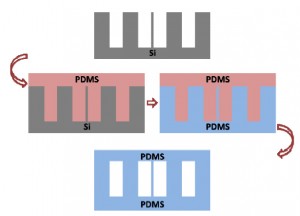
Moulding PDMS with a PDMS master replicated from the microfabricated silicon directly can overcome the aforementioned problems, as illustrated in Fig. 1c. It has been developed by silanizing the PDMS master with tridecafluoro- 1,1,2,2- tetrahydrooctyl- 1- trichlorosilane (in vacuo, 8h[2] or overnight[3]). In this Tip, we optimized the PDMS moulding process with the PDMS replica as the master. The optimal protocol is simple and easy to establish in any labs.
Fig. 1 Moulding PDMS with microfabricated silicon as master. (a) Schematic illustration of the lag effect induced leakage and bonding problems existed in the traditional soft-lithography when the PDMS is replicated from the microfabricated silicon master directly. (b) SEM photo of the microfabricated silicon master used in the present work (with the tilting angle of 45o). Inserted SEM photos give the morphology comparison between the etched silicon surface and the original one. (c) Schematic illustration of the moulding PDMS process with a PDMS master.
What do I need?
Microfabricated silicon, aluminum foil (Select HORECATM, Jinweiyuan Hotel Supplies Co. ltd.), mould release reagent (Micro90®, International Products Corporation, USA), PDMS (Sylgard 184; Dow Corning Co., MI), detergent (commercial available detergent, White CATTM, White Cat co. ltd.), ethanol (MOS grade, Beijing Chemical Reagent Institute).
What else should I know?
Process optimization
The present protocol contains two PDMS moulding processes: The first one is to construct the PDMS master from the microfabricated silicon while the second to make the final PDMS replica directly from the so-prepared PDMS master.
Considering the Corona-triggered PDMS-PDMS bonding technique [4], which will be adopted in the subsequent PDMS-microfluidic device construction, curing at 60oC for an hour of the PDMS pre-polymer prepared following the manufacture guideline was selected as the second PDMS moulding recipe. In this chips and tips, the first PDMS moulding process and the surface treatment of the PDMS master were optimized.
1) Optimization of the first PDMS moulding process
The first PDMS moulding process was optimized for the PDMS master preparation as shown in Table 1. Based on the above experiments, we found the optimal recipe for the first PDMS moulding process was curing the PDMS pre-polymer at 120oC for an hour with the mass ratio (Base to Curing agent) of 5:1. (Condition No.4)
2) Optimization of the surface treatment of the PDMS master
Surface treatment is another important factor for the PDMS moulding and was optimized as listed in Table 2. The results indicated that detergent dissolved in 75% ethanol (about 10 w.t.%) was the optimal recipe for the second PDMS moulding process. (Condition No.3) Herein, we name it the modified mold release agent. In later work we also use it for pre-treatment of the microfabricated silicon master.
How do I do it?
1. Make a holder with aluminium foil, according to the shape of the microfabricated silicon master. [5]
2. Mix the PDMS according to the manufacturer’s procedure, but with a mass ratio of the Base to the Curing agent of 5:1.
3. Pre-treat the microfabricated silicon master with the modified mold release agent.
4. Dry the microfabricated silicon master with nitrogen and put it into the holder.
5. Pour the PDMS pre-polymer into the holder, covering the whole microfarbicated silicon master, and then place the holder in an oven at 120oC for an hour.
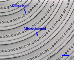
6. Gently peel the PDMS replica (the PDMS master in the second PDMS molding process) off from the microfabricated silicon master. (Fig.2)
7. Treat the PDMS master with the modified mould release agent. For the deep holes (e.g. some holes with the depth of 100?m in Fig.2), treat the master with the modified mould release agent in the vacuum.
8. Place this PDMS master in a Petri dish, with the moulded-side upwards.
9. Mix PDMS prepolymer again according to the standard manufacturer’s procedure with a mass ratio of the base to the curing agent of 10:1.
10. Pour the PDMS mixture into the Petri dish, covering the whole PDMS master, and then cure at 60oC for an hour.
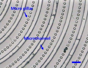
11. Carefully peel the PDMS replica (Fig.3) off from the PDMS master for the subsequent experiments.
Acknowledgements
This work was financially supported by the 973 Program (Grant No. 2009CB320300).
References
[1] A. Estévez-Torres, A. Yamada and L. Wang, An inexpensive and durable epoxy mould for PDMS, Chips & Tips (Lab on a Chip), 22 April 2009.
[2] J. R. Anderson, D. T. Chiu, R. J. Jackman, O. Cherniavskaya, J. C. McDonald, H. Wu, S. H. Whitesides and G. M. Whitesides, Fabrication of Topologically Complex Three-dimensional Microfluidic Systems in PDMS by Rapid Prototyping, Anal. Chem., 2000, 72, 3158-3164.
[3] J. L. Tan, J. Tien, D. M. Pirone, D. S. Gray, K. Bhadriraju, and C. S. Chen, Cells lying on a bed of microneedles: An approach to isolate mechanical force, Proc. Natl. Acad. Sci. U. S. A., 2003, 100(4), 1484-1489.
[4] C. Yang, W. Wang, and Z. Li, Optimization of Corona-triggered PDMS-PDMS Bonding Method, in Proceedings of the 4th IEEE International Conference on Nano/Micro Engineered and Molecular Systems, 319-322.
[5] A. O’Neill, J. Soo Hoo and G. Walker, Rapid curing of PDMS for microfluidic applications, Chips & Tips (Lab on a Chip), 23 October 2006.


