Christopher Moraes, Yu Sun, and Craig A. Simmons
Department of Mechanical and Industrial Engineering, University of Toronto, Toronto, Ontario, Canada
Why is this useful?
An often-touted advantage of microfluidic systems is the small volumes of reagents required. However, the world-to-chip interconnects often require fluid volumes orders of magnitude greater than those used within the microfluidic channels themselves. Moreover, commonly used interconnect schemes are either expensive; custom-manufactured or require substantial additional fabrication efforts; or are severely prone to failure, leaks and clogging.
This tip presents a simple, inexpensive and easily-accessible method to manipulate small volumes of fluid in standard microfabricated PDMS channels, without the use of a connector scheme. Though it cannot be used to produce well-controlled or continuous long-term flow, we have found it ideal for applications such as device pre- and post-processing (e.g., chemical-based surface modification and immunostaining). The technique is simple and robust, and has been used effectively both by experienced researchers and untrained, minimally supervised undergraduate students in a teaching lab.
What do I need?
- Fully cured microfluidic PDMS device
- Glass substrate
- PDMS punch
- 1 mL Pasteur pipette bulb (Sigma-Aldrich, product Z111589)
- Pipettes and tips
- Kimwipes
How do I do it?
1. Punch an access port into the PDMS device at the channel entry and exit points. The size of the hole can be selected based on the reagent volume required by the device. In this example, we used a 1/8″ diameter punch.
2. Bond the patterned PDMS layer to a glass slide, as per standard procedure for PDMS device fabrication.
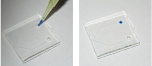
3. Pipette a small quantity of reagent directly into the access port (Figure 1; blue dye used for this demonstration). We have successfully used this technique with volumes as low as 4 mu.gifL.
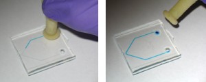
4. Place the Pasteur pipette bulb (Figure 2) over the punched reservoir and gently hold it down so it forms a conformal seal around the reservoir (Figure 3). Provided the area around the access port is fairly flat, maintaining a seal is typically not a problem.
5. Squeeze the bulb gently to apply positive pressure and cause the fluid to flow into the microchannels (Figure 4).
6. Channels can be cleared by first pipetting away excess fluid from the access port, and then using the Pasteur pipette bulb to force air through the channel, while wicking away the expelled liquid at the exit port with a Kimwipe.
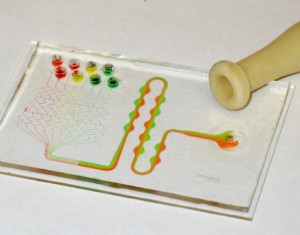
The Pasteur pipette bulb can also be used to apply a negative pressure by squeezing it first, placing it over the channel access port, and gently releasing the bulb. In Figure 5, we used this technique to drive flow in a standard microfluidic gradient generator system: negative pressure is applied at the outlet channel port, drawing eight separated reagents through the mixing channels.


