Gregory A Cooksey1 and Glynis Mattheisen2
1 Biochemical Science Division, National Institute of Standards and Technology, Gaithersburg, MD
2 Louisiana State University, Baton Rouge, LA
Why is this useful?
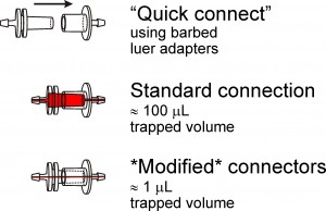
Luer adapters are convenient tools to rapidly and reversibly connect tubing from fluid reservoirs to microfluidic devices. One problem associated with the use of these adapters is that they trap considerable dead volume (approx 100 µl), which dramatically increases the time required to rinse away one fluid when another fluid is to be delivered down the same line. Another common shortcoming of leur adapters is that they are only available for 1.59 mm (1/16″) and larger inner diameter (ID) tubing. We demonstrate how to modify luer adapters to fit almost any size tubing while dramatically reducing the dead fluid volume trapped inside the connector.
What do I need?
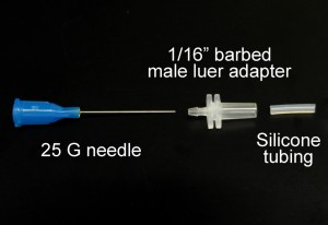
- 25 mm or longer needle or stainless steel tubing. We use blunt 25 gauge needles (McMasterCarr # 75165A761). Use extreme care with exposed needles!
- Polypropylene 1/16 in. barbed male luer adapter (Cole Parmer #R-45503-07)
- Silicone tubing with large enough ID to slip over needle but small enough outer diameter (OD) to fit inside luer adapter. We use 0.8 mm ID silicone tubing (Cole Parmer #R-06411-60)
- Poly(dimethylsiloxane) (PDMS) (Sylgard 184, Dow Corning)
- Tubing to attach to the connectors. We use 0.51 mm ID tygon microbore tubing for 25 gauge needles (Cole Parmer #R-06418-02)
- Dremel 300 (Dremel) or similar tool with cutoff wheel (Dremel #409)
How do I do it?
1. Insert the needle into the barbed end of the 1/16 in. barbed male luer adapter.
2. Thread about 15 mm of silicone tubing onto the needle and push the tubing to the base of the adapter using tweezers. This keeps the needle centered in the adapter, and the silicone tubing bonds well to the PDMS. The tubing should stick out of the adapter about 3mm, which accounts for extra dead space that exists in needle hubs and other female luer adapters.
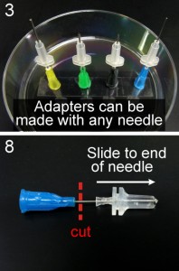
3. Place the hubs of the needles you’ve made onto a dish standing upright. Double-sided tape on the bottom of the dish will help keep the needles upright.
4. Fill the inside of the luer adapters with PDMS. We find it helpful to use a syringe (with an 18 G needle) to inject PDMS into the adapters. At this point it is recommended to de-gas the PDMS by placing it in a vacuum jar for several minutes.
5. Place the dish in an oven at 70ºC to cure for at least 2 hours. Check after about an hour to make sure the luer hubs stayed filled with PDMS. You may have to add some additional PDMS if some has leaked out the barbed end.
6. Remove the needle from the dish and clear away excess PDMS from the base of the needle and the outside of the adapter.
7. Push the adapter to the tip of the needle.
8. Cut away the needle luer hub. A wire cutter can be used, but we prefer using a Dremel tool fitted with a cutting wheel. It is less likely to compress the tubing closed. Polishing the end of the needle with the cutting wheel is also recommended.
9. Insert the needle extending from the barbed end of the adapter into 0.51 mm ID Tygon tubing.
What else should I know?
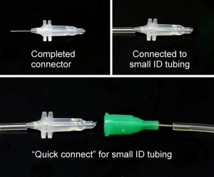 “Quick connects” for the same or different ID tubing can be made by plugging the connector into the luer hub of a blunt needle that fits tightly inside the desired tubing.
We have also tried filling the luer hubs with PDMS and curing them prior to inserting needles or stainless steel tubing. Because the needles are flexible, we find it difficult to keep the needles straight through the center of PDMS core. This method also typically plugs the needle, so a new needle would be necessary to replace the coring needle.
Disclaimer: Certain commercial equipment, instruments or materials are identified in this report to specify adequately the experimental procedure. Such identification does not imply recommendation or endorsement by the National Institute of Standards and Technology, nor does it imply that the materials or equipment identified are necessarily the best available for the purpose.


