Archive for November, 2009

A simple and economical holder for casting PDMS chips

Gang Li*, Qiang Chen and Jianlong Zhao

Shanghai Institute of Microsystem and Information Technology, Chinese academic of Sciences, Shanghai, China

Why is this useful?


To fabricate PDMS chips, one usually pours an un-cured PDMS mixture into a Petri dish or an aluminum foil tray containing the patterned master, and then cures for 2 h at 85°C. However, these casting dishes or trays present some cost problems. Often a relatively high consumption of PDMS is demanded for these casting holders because quite a part of PDMS will seep into the gap between the wafer and trays due to capillary forces during PDMS pouring. On the other hand, the seepage of PDMS under the master wafer may tilt the master causing the thickness of the PDMS mold to vary from one side to the other. Furthermore these casting dishes or trays are generally throw-away holders for casting PDMS chips, which also increases the fabrication cost of PDMS chips.

This tip presents a new casting holder, made of a hollow plate whose bottom is enveloped by an adhesive tape. This casting holder can simplify the operation of releasing the cured PDMS casting, and minimize the consumption of PDMS. In addition, this holder can be used to fabricate double-side flat PDMS chips by placing a flat substrate on its top.

What do I need?


  • Circular hollow plate (home-made of PMMA)
  • Adhesive tape (Nitto Denko Corp., SPV-224)
  • PDMS (Dow Corning Sylgard 184)
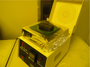
  • Hotplate (Chemat Technilogy Inc., KW-4AH hotplate)
  • PET (Polyethylene terephthalate) film and flat glass slide (for optional double-side flat PDMS chips)  

What do I do?


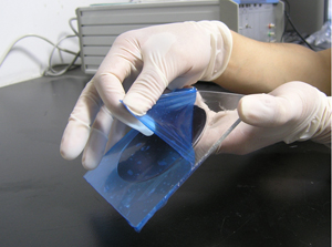
1. Seal the bottom opening of the hollow plate with adhesive tape to form a casting holder (Figure 1), whose diameter is a little bigger than that of master wafer.

Figure 1

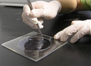
2. Place the master in the holder, and carefully apply a pressure to attach it to the tape, preventing any gaps from forming at the interface (Figure 2).

Figure 2

3. Mix the PDMS according to the manufacturer’s procedure [1].

4. Pour the PDMS mixture in the casting holder, and then place the holder on a hotplate at 85ºC for 2 hours.

5. Once the PDMS is cured, remove the holder from the hotplate and allow it to cool to room temperature.

6. Gently peel off tape from the bottom of holder (Figure 3).

Figure 3

7. Carefully cut around the edge of the PDMS mold using a sharp scalpel, and separate the PDMS from the holder (Figure 4).

Figure 4

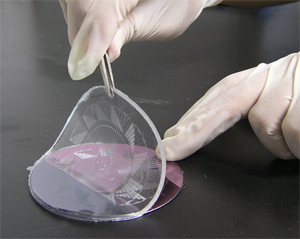
8. Finally, peel the PDMS mold from the master wafer (Figure 5).

Figure 5

9. (Optional, for double-side flat PDMS chips) Prepare the casting holder as described above,  pour the PDMS mixture in the casting holder until the level of PDMS is a little higher than the top of holder, and then carefully drop a PET film onto the prepolymer mixture (Figure 6), which provides an easy way to remove the cover plates from the PDMS molds after curing.

Figure 6

10. Apply a pressure on the top of the film with a stack of glass slides and steel block to planarize the surface of the PDMS chips, and then cure the PDMS by placing the holder on a hotplate (Figure 7).

Figure 7

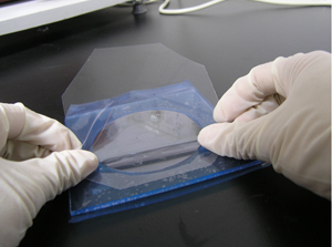
11. After curing, remove the glass slide and steel block from the top of holder, and then gently peel off the tape and PET film from the PDMS block (Figure 8).

Figure 8

12. Finally, separate the PDMS block from the holder and peel the PDMS mold from the master.

Acknowledgements


This material is based upon work supported by the Major State Basic Research Development Program of China (No. 2005CB724305), and the National High Technology Research and Development Program of China (No.2006AA02Z136).

References


[1] Dow Corning Product Information, “Information about Dow Corning® brand Silicone Encapsulants,” 2005.

Digg This
Reddit This
Stumble Now!
Share on Facebook
Bookmark this on Delicious
Share on LinkedIn
Bookmark this on Technorati
Post on Twitter
Google Buzz (aka. Google Reader)

“Custom made” production of cheap Luer lock adapters for chip-to-syringe interfacing

Stefania Mazzitelli, Stefano Focaroli and Claudio Nastruzzi
Department of Chemistry and Technology of Drugs, University of Perugia, Perugia, Italy

Why is this useful?


One of the standard procedure to pump solutions, emulsions or suspensions, into microfluidic chips is based on the use of syringes, through peristaltic pumps. Syringe pumps are usually preferred over peristaltic ones, for their ease of use, for the accurate and stable control of the flow rate and, finally, for the possibility to employ sterile conditions.

Luer taper is a standardized system of small-scale fluid fittings used for making leak-free connections between a male-taper fitting and its mating female part on medical and laboratory instruments, including hypodermic syringe tips and needles or stopcocks and needles. The fitting is named after the 19th century German medical instrument maker Hermann Wülfing Luer.

There are two varieties of Luer Taper connections: Luer-Lok and Luer-Slip; Luer-Slip fittings simply conform to Luer taper dimensions and are pressed together and held by friction (they have no threads). Luer components are manufactured either from metal or plastic and are available from many companies worldwide but they are usually sold in few standard dimensions and are relatively expensive.

In this Tip we present a way to easily produce a variety of “on demand” Luer connectors, including: (a) female Luer x female Luer adapter, (b) female Luer x female Luer elbow, (c) male Luer x male Luer adapter, (d) male Luer x male Luer elbow, (e) male Luer x female Luer coupler and finally (f) male Luer x female Luer elbow.

What do I need?


  • 1-30 mL polypropylene syringes (Artsana, Italy) [1]
  • tubing: Upchurch Scientific® FEP (fluorinated ethylene-propylene); Tub FEP Nat 3/16 x .125 x 20ft (Upchurch Scientific, UK; No.: 1524) [2]
  • tubing: Timmer-Pneumatik GmbH; H-PTFE-4/2 mm (OD/ID)-blue, catalog Timmer 2001 [3]
  • Aesculap scalpel blades fig. 23, carbon steel, package of 100 pieces in dispenser package [4]
  • Aesculap scalpel handle fitting no. 4 for blades 18-36, 135 mm, 5 ¼, [5]
  • Black & Decker heat gun, model kx1693, [6]

What do I do?


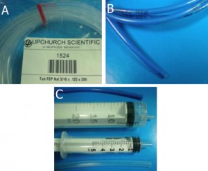
1. Tubing (A, B) and template syringes (C) are used for the production of Luer connectors. A: FEP (fluorinated ethylene-propylene) tubing; B: H-PTFE tubing.

Figure 1

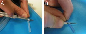
2. Tubing cutting by scalpel. The length of the Luer connector can be adjusted depending on the specific needs of the researcher (for instance, the distance between the syringe pump and the chip). Note that in the case of H-PTFE tube (B), the cutting is made with an angle of 45° with respect to the tube major axis.

Figure 2

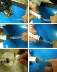
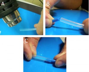
3. Preparation of a female Luer adapter: A. Heating of a FEP tube end by heat gun for 1-3 min; B-D. Press and insert the male Luer of a polypropylene syringe into the heated tube. E. Cool down the tube by tap water. F. Permanent deformation of the tube end.

Figure 3

4. Preparation of a male Luer adapter: A. Heating of a FEP tube end by heat gun for 1-3 min; B-C. Press and insert the H-PTFE tube end (cut at 45°) into the heated FEP tube, cool down the tube connection by tap water until a permanent deformation is reached.

Figure 4

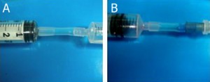
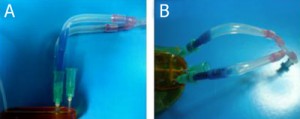
5. Examples of female Luer X female Luer adapter (A) and female Luer X male Luer adapter (B).

Figure 5

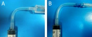
6. Examples of female Luer X female Luer elbow (A) and female Luer X male Luer elbow (B).

Figure 6

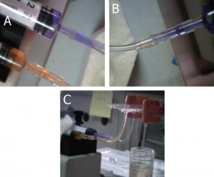
7. Examples of the use of female Luer X female Luer adapter to connect syringes to a commercial chip.

Figure 7

8. Examples of the use of female Luer X male Luer elbow to connect syringes to a homemade chip.

Figure 8

References


[1] http://www.artsana.com
[2] http://www.upchurch.com
[3] http://www.pneumatica-it.timmer-pneumatik.de
[4] http://www.chirurgische-instrumente.info/en/search.html?kw=bb523
[5] http://www.chirurgische-instrumente.info/en/search.html?kw=bb084r

Digg This
Reddit This
Stumble Now!
Share on Facebook
Bookmark this on Delicious
Share on LinkedIn
Bookmark this on Technorati
Post on Twitter
Google Buzz (aka. Google Reader)