Archive for October, 2009

A novel method for fabrication of reusable microfluidic interconnects

Koesdjojo, M.T., Mandrell, D.T., Tennico, Y.H., Remcho, V.T.*
Department of Chemistry, Oregon State University, Corvallis, Oregon, USA

Why is this useful?


The lack of an efficient interface, or interconnect, between microfluidic devices and the macroscale world is a major impediment to the broader application of micro total analysis system (µTAS). There are a number of current products and solutions available that seek to address this issue. An example of a simple approach is the direct integration of tubing or a syringe needle into the microchip inlet using epoxy glue.[1] However, direct connection to the inlet reservoir using an epoxy often leads to clogging of the microchannels. Commercially available connections to microfluidic chips and devices, such as the NanoPort from Upchurch Scientific (Oak Harbor, WA, 98277, USA), accommodate these needs by use of a threaded nut and ferrule system. These fittings can be integrated onto chip reservoirs by means of adhesive rings or epoxy glue.[2] The drawback to this method is that NanoPorts require the use of an epoxy glue that takes time to cure and is non-removable, or an adhesive ring that is not compatible with many solvents. Another drawback is that the epoxy requires high temperatures for complete curing, making it incompatible with low glass transition (Tg) polymers.[3] Commercial edge connectors provide efficient interfacing and allow rapid connections and reusability.[4] However, they are designed to be interfaced to a standard microchip format; which limits the compatibility of other chips with different geometries layout or sizes.

This tip presents an alternative approach to making simple, cost-effective universal interconnects. The device was developed to allow for standard compression tubing connectors, such as those available from Upchurch, to be interfaced with microfluidic chips. A standard breadboard fixture was used to compress the ports against the chip to apply sealing pressure, preventing leaks at the interface.  This method allowed for connections to be made without glue, epoxy, or any form of bonding, enabling the components to be easily and quickly reused or reconfigured without the need to machine new fixtures or re-bond ports. The working pressure of these ports was tested with a syringe pump, and withstood pressures in excess of 1000 psi without any signs of leakage or failure.

What do I need?


  • 0.25 and 0.5 inch thick plastic substrates such as polycarbonate (PC)
  • #21, #9 drill bits
  • 10-32 bottoming tap
  • 1mm drill bit
  • 1/16 inch PEEK or Teflon tubing
  • stainless steel 10-32 socket head cap screws
  • 1/32 inch Silicon o-rings
  • Upchurch 10-32 ferruled fittings (F-333)

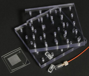
Figure 1. Picture of system components

What do I do?


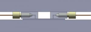
1. The first component was a port which allowed a standard ferruled connector to be attached perpendicular to the microfluidic device.  It contained a threaded portion for the fitting and a fluid path with small port on the bottom for the interface (Figure 2). The port was manufactured using 0.25 inch PC, but can be made of any material thick enough to allow room for the ferruled connector between the compression plates.  It was machined to size using a knee mill.  The threaded port was drilled with a #21 drill bit, then tapped with a 10-32 bottoming tap.  The fluid paths were drilled using a 1mm drill bit (substitute any drill to achieve the desired internal volume).  An o-ring was then placed in the threaded hole to ensure a tight seal against the ferruled fitting.

Figure 2. Interconnect section view (left) and the solid model (right).

2. The second component was a breadboard clamp which applied pressure between the microfluidic device and interconnects (Figure 3). This breadboard approach was particularly useful for prototyping devices having different dimensions and port locations, as interconnects could easily be relocated. A wide variety of bolt locations in the clamping plates allowed for a wide variety of component sizes and configurations. The breadboard clamp assembly was manufactured by cutting 0.5 inch thick PC into two five inch squares.  Using the knee mill, a one inch grid of holes was drilled and taped on one plate with the #21 drill and 10-32 tap.  Clearance holes were drilled on the same grid, using a #9 drill bit, in the second clamping plate.

Figure 3. Side view of a chip, interconnects, and the compression plates.

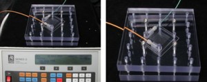
3. The 90° interconnect ports were placed on each of the reservoir holes of a microchip. The ferrules were connected to their respective tubing.  The top plate of the breadboard clamp was installed and using the holes closest to the sides of the chip, 10-32 stainless steel screws were inserted to apply even pressure by clamping the entire fixture.  Figure 4 shows the setup used to pressure-test the manufactured ports.

Figure 4. Setup used for pressure testing (left) and the close up view of a chip in the device (right).

References


[1] T. Das, Interfacing of microfluidic devices, Chips & Tips (Lab on a Chip), 27 February 2009.
[2] http://www.upchurch.com/
[3] J. Greener, W. Li, D. Voicu, E. Kumacheva,  Reusable, robust NanoPort connections to PDMS chips, Chips & Tips (Lab on a Chip), 8 October 2008.
[4] http://www.dolomite-microfluidics.com/

Digg This
Reddit This
Stumble Now!
Share on Facebook
Bookmark this on Delicious
Share on LinkedIn
Bookmark this on Technorati
Post on Twitter
Google Buzz (aka. Google Reader)

Plug-and-play reservoirs for microfluidics

Christopher Y. Wong*, Georgian Ionut Ciobanu*, Mohammad A. Qasaimeh, and David Juncker
Micro and NanoBioEngineering Laboratory, Biomedical Engineering Department, Faculty of Medicine, McGill University, Montreal, Canada.
* Authors contributed equally

Why is this useful?


Microfluidic and lab-on-a-chip (LOC) devices are typically connected to external sample reservoirs. A significant issue for LOC devices is interfacing multiple sample reservoirs and connecting them both to external pressure controllers or syringe pumps and to the microfluidic chip [1,2]. Researchers typically use home-made reservoirs and interfacing them to the chip and the controllers requires specialized skills and training and/or additional fabrication steps.[3,4] Often the connections are unreliable and leaky, and as a consequence much time is lost in setting them up and it is difficult to add or remove connections from the reservoirs.

Here we introduce a “plug-and-play” reservoir that allows for multiple connections to be simply plugged in. The reservoirs are made using off-the-shelf threaded microcentrifuge tubes and screw-on septum caps. Needles, capillaries and steel tubing can be inserted one at a time – or in combination – through the cap’s septum and used to connect the reservoir to a pressure source and to one or several inlets of a microfluidic chip. The connectivity between reservoir and pressure source(s) and chip(s) can be adapted to specific needs, for example to form a reservoir with a single input and a single output, or with multiple inputs and outputs. Reservoirs with single or multiple input/output lines can be switched easily by by unscrewing the microcentrifuge tube and screwing the cap with the capillaries on another microcentrifuge tube containing a different solution.

The reservoirs are cheap, disposable, easy to assemble, and robust enough to support pressures up to 345 kPa (and even higher pressures with the variant described in the supplementary material) while having almost no dead volume. The connection of reservoirs to microfluidic chips – or to other reservoirs so as to form complex circuits – can be performed in a matter of seconds. Arrays of off-chip reservoirs can be assembled within racks and many lines can be connected at high density to a microfluidic chip. These plug-and-play reservoirs are a versatile solution to the world-to-chip interface and should find widespread application for microfluidic experimentation.

What do I need?


For the reservoir:

  • threaded screw cap with membrane/septum [5]
  • threaded microcentrifuge tube (any volume, as long as it has the same thread type as the cap) [5]

For the connections:

  • sharp hypodermic needle with Luer-Lock (any size from 23 to 16 gauge) [6]
  • 1/16″ ID Tygon tubing or other preferred tubing [7]
  • male Luer-lock to 1/16″ ID hose barbed tubing adapters [7]
  • glass capillary (Note: OD of glass capillary needs to be smaller than ID of needle) [8]

Optional for other connection types (shown in supplementary materials):

  • 0.0250″ OD hollow steel tubing [9]
  • 0.0200″ ID microbore Tygon Tubing [10]

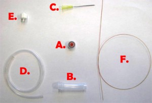
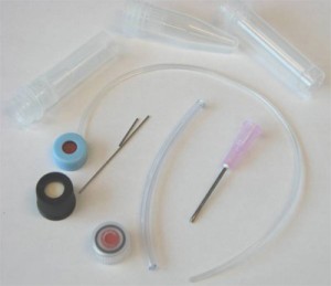
Fig. 1 shows the required parts. Fig. S1 in the supplementary materials shows the alternative options in our laboratory of microcentrifuge tube sizes and input/output connection types. (A) Threaded screw cap with membrane/septum [5]. (B) Threaded microcentrifuge tube [5]. (C) Sharp 20G1½ hypodermic needle with Luer-Lock [6]. (D) 1/16″ ID Tygon tubing [7]. (E) Male Luer-lock to 1/16″ ID hose barbed tubing adapter [7]. (F) Glass capillary of 350 µm OD [8].

Figure 1. Different parts used to make the reservoir.

What do I do?


1. In order to insert a glass capillary to serve as an output, use a sharp hypodermic needle with an inner diameter (ID) that is just larger than the capillary’s outer diameter (OD). Insert the needle into the membrane screw cap and then slide the capillary through the needle, as shown in Fig. 2.

Figure 2. Insert a needle into the membrane screw cap and pass the glass capillary through the needle.

2. Screw the cap onto a reservoir of the desired size and then remove the needle while holding the capillary in place, as shown in Fig.3. Repeat steps 1 & 2 for every additional glass capillary connection required.

Figure 3. Pulling the needle out but keeping the capillary in place fixed by the membrane.

3. Insert the input pressure needle to appropriate depth (see next section for details) and connect to the Tygon tubing to the needle using the Luer-lock to tubing adapters, as shown in Fig.4. Repeat this step for every additional Tygon tubing connection required.

Figure 4. Reservoir with a needle connection interfaced to a glass capillary (typically connected to the microfluidic chip) and Tygon tubing with a Luer-lock adaptor (typically connected to the pressure source) which can be used to control the flow from the reservoir to the chip.

4. The reservoir is completed. Unscrew the cap from the container and fill it with your reagent and screw the cap back on.

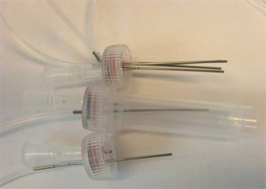
5. (Optional step) Instead of using a glass capillary, a steel tube connected to Tygon microbore tubing can be used. We used 0.0250″ OD steel tubing, inserted into 0.0200″ ID Tygon tubing and then forced the pin through the septum, as seen in Fig. 5. Multiple steel-Tygon tubing connections can be connected to one septum as shown in Fig. S2.

Figure 5. Steel tubing and Tygon microbore tubing connected to a reservoir.

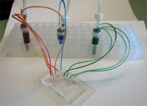
6. Connect the 1/16″ Tygon tubing to the pressure source and the capillary (or the microbore Tygon tubing) to the chip. Make sure to create slightly smaller sized holes for the input connections on the chip to create a tight seal. When using multiple reservoirs, they can be placed into microcentrifuge tube racks for easy handling (Microtube Storage Racks), as shown in Fig. 6.

Figure 6.  A picture of a chip connected to three reservoirs placed on a storage rack, each with an independent input line and multiple outputs.

7. Everything is now ready to use!

What else should I know?


This setup is simple, easy to build and can be done in less than a minute. Depending on the cap, the membrane/septum provides an airtight seal, but after inserting and removing needles more than a few times, especially with larger needles, leakage becomes apparent. Since the system is pressure controlled, a small leakage rate relative to the supply flow rate can be tolerated. Only a limited number of connections, up to 10 in our experience, can be connected to a single cap or else leakage becomes excessive. The reservoirs work well up to 345 kPa, and for higher pressure applications solid caps can be used as described in the supplementary material.

It is important to maintain the needle connected to the pressure source above the liquid surface in order to prevent the formation of bubbles. Be careful of the sharp points and remember to dispose of the needles properly.

Supplementary materials


Figure S1. The different available options (excluding glass capillaries) in our laboratory of microcentrifuge tubes sizes, membrane caps, steel tubing, and input/output connections.

Figure S2. Multiple tubing outputs through multiple inserted steel tubing.

The presented setup above was not tested at pressures higher than 345 kPa, and at pressures above 140 kPa, there was minimal gas leakage. However, we have developed another setup that works without any leakage, even at 345 kPa, but requires several minutes to make and a precision micro-drill. This setup does not use a membrane cap, but a conventional screw cap without a membrane. Using suitable micro-sized drill bits, different sized holes can be made in the micro tube or the cap. After inserting the output capillaries or steel tubing and the input syringe needle, Instant Krazy glue [10] is applied to affix the inputs and outputs at the precise place. Dual melt glue [11] is then applied to seal the terminals from air/liquid leaks. The final setup is shown in Fig. S3.

We mention here that this setup is permanent and should be robust at high pressure applications. At the same time, it requires a precision micro drill, more time to make, and it is less flexible in the sense that it is harder to modify the interface.

Figure S3. High pressure off-chip containers with one Luer-Lock input and one glass capillary output at the bottom.

References


[1] S. Li and S. Chen, IEEE Trans. Adv. Packag., 2003, 26, 242-247.
[2] R. Lo and E. Meng, Sens. Actuators, B, 2008, 132, 531-539.
[3] T. Liu, E. V. Moiseeva and C. K. Harnett, Integrated reservoirs for PDMS microfluidic chips, Chips & Tips (Lab on a Chip), 22 April 2008.
[4] T. Das et al., Interfacing of microfluidic devices, Chips & Tips (Lab on a Chip), 27 February 2009.
[5] Sarstedt AG & Co.: http://www.sarstedt.com/
[6] BD: http://www.bd.com/
[7] McMaster-Carr Supply Company: http://www.mcmaster.com/
[8] Polymicro Technologies: http://www.polymicro.com/
[9] New England Small Tube: http://www.nesmalltube.com/
[10] Small Parts, Inc.: http://www.smallparts.com/
[11] Krazy Glue: http://www.krazyglue.com/
[12] The Stanley Works: http://www.stanleyworks.com/

Digg This
Reddit This
Stumble Now!
Share on Facebook
Bookmark this on Delicious
Share on LinkedIn
Bookmark this on Technorati
Post on Twitter
Google Buzz (aka. Google Reader)