Boyang Zhang1, Milica Radisic1, Shashi Murthy2
1Department of Chemical Engineering and Applied Chemistry, University of Toronto, Toronto, ON, Canada
2Department of Chemical Engineering, Northeastern University, Boston, MA, USA
Background
The operation of microfluidic systems often requires sequential injection of more than one type of solution with a syringe pump. For instance, many adhesion-based cell-separation devices require additional injection of washing buffer or/and cell-releasing buffer after cell injection [1, 2]. Minimal flow disturbance to the system during switching to the next solution is critical for proper operation of such devices. Switching syringes during pumping will inevitably stop the flow and risk introducing bubbles to the device. Simple four-way valves are traditionally used in such cases [3]. However, many commercially available four-way valves have large dead volumes and long residence times that make them incompatible with microfluidic systems.
Why is this useful?
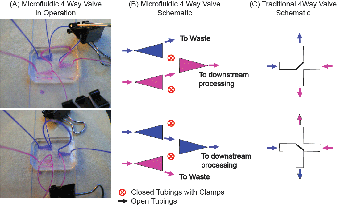
Here we present a simple, three-chamber microfluidic system with interconnected tubings (Figure 1) as an alternative to the traditional 4-way valve used for switching between solutions during experiments. For microfluidics applications, our system has the advantages of (1) allowing for switching between two solutions with minimal disturbance to the flow, (2) greatly reduced risk of introduction of unwanted air bubbles into the system, and (3) greatly reduced dead volume. The total volume of our system is two orders of magnitude less than a typical, commercially available 4-way valve (~1 µL as compared to ~1 mL) [5]. Our valve system is simple and cost-effective, as it utilizes clamps (binder clips) to block selected tubings. We have also shown that the tubings are strong enough to withstand several iterations of clamping and release. Lastly, this method can be scaled up to control the flow of more than two types of solutions, simply by adding more chambers and clamps.
What do I need?
- Clamps (Binder Clips)
- Tygon tubing (any size)
- PDMS silicone elastomer base and curing agent (Sylgard 184, Dow Corning)
- Glass slides, pre-cleaned (Fisher Scientific, 75mm x 50mm x 1mm, Cat. No. 12-550-C)
- Scotch tape (3M Scotch® Transparent Tape 600)
What do I do?
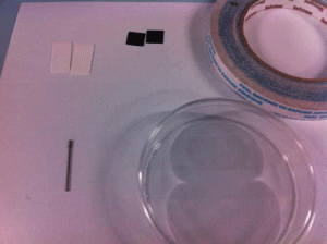
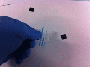
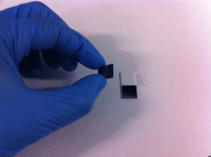
(1) Fabricate the master for the device. The device includes three triangular shaped chambers. The exact dimensions of these chambers are not critical and should be tailored to the specific experiment. In this case, triangular shaped channel with height of 40 μm and edge-width of 3 mm is used for flow rate up to 80 μl/min. The master can be fabricated with scotch tape which would greatly speed up the fabrication step especially for design with only large features [4].
(1) Pour PDMS over the master and cure to create a PDMS-based device.
(2) Drill holes as indicated in Figure 1 and bond the device to a glass slide.
(3) Insert the tubing into the holes, again following Figure 1.
(4) Fill the device with selected solution and clamp shut the selected tubing.
(5) To switch solutions during an experiment, simply switch the position of the clamps as shown in Figure 1.
Figure 1. Device schematic: (A) Microfluidic 4 way valve with color dyes to demonstrate the function of the clamps to stop and re-route flows. (B) Schematic of the device in operation. (C) Traditional concept of 4 way valves.
References
1. B. D. Plouffe, M. A. Brown, R. K. Iyer, M. Radisic and S. K. Murthy, Controlled capture and release of cardiac fibroblasts using peptide-functionalized alginate gels in microfluidic channels, Lab Chip, 2009, 9, 1507-10.
2. B. D. Plouffe, M. Radisic and S. K. Murthy, Microfluidic depletion of endothelial cells, smooth muscle cells, and fibroblasts from heterogeneous suspensions, Lab Chip, 2008, 8, 462-72.
3. L. Kim, M. D. Vahey, H.-Y. Lee and J. Voldman, Microfluidic arrays for logarithmically perfused embryonic stem cell culture, Lab Chip, 2006, 6, 394-406.
4. A. B. Shrirao and R. Perez-Castillejos, Simple Fabrication of Microfluidic Devices by Replicating Scotch-tape Masters, Chips & Tips (Lab on a Chip), 17 May 2010.
5. 4 WAY ACTUATION VALVES, Parker Hannifin Corp, 04 October 2011.


