Jean-Christophe Baret
Institut de Science et d’Ingénierie Supramoléculaires (ISIS),
Université de Strasbourg, CNRS UMR 7006, Strasbourg, France
jc.baret[at]unistra.fr
Why is this useful?
In suspension, cells, beads and particles tend to sediment at a speed given by the balance of viscous drag and gravity force. In classical biological experiments, the most straight-forward solution to keep cells in suspension is to shake large volumes. This type of system is relevant at high Reynolds number but is not very compatible with the classical systems used to inject small amounts of liquid in confined geometries, such as microfluidic systems.
Another common way to prevent sedimentation is to match the densities of the particles and the carrier fluid, or to increase the viscosity of the carrier fluid to increase sedimentation times. However, these solutions are not always suitable due to the biological or physical constraints of a microfluidic experiment. For example, increasing viscosities increases the pressure drop in microchannels, and additives for density matching are not always biocompatible.
Previously in the Chips and Tips section a system has been described for cell injection [1]. With a similar system, we observed that sedimentation along the tubing binding the syringe reservoir to the chip hinders good mixing of the cells. This tubing should therefore be as short as possible, which is sometimes incompatible with the large footprint of the syringe pumps or other equipment around the microfluidic chip. Interestingly, in another Chips and Tips section, a system for temperature control of syringe pumps has been described [2]. The idea there was to use a syringe pump to pump liquid in order to move the piston of another syringe placed in a temperature-controlled bath. This system still showed problems related to the length of the connection tubing to the chip.
Here we combine both systems [1,2] to inject cells, beads and particles efficiently into microfluidic devices using small amounts of liquids (typically ~1 mL). The cells are initially placed in a syringe close to the chip and are automatically shaken inside the syringe using a small motor and a magnet. This syringe is then remotely actuated by another syringe mounted on a syringe pump [2] which reduces the footprint of the injection system in the vicinity of the chip. The tubing length from the syringe containing the cells to the chip can then be as small as 5 cm, which reduces the residence time of cells in the tubing and therefore reduces sedimentation.
What do I need?
- Syringes: BBraun Injekt (2 mL or 5 mL)
- Syringe needles: Terumo NEOPLUS 23G
- Tubing: Fisher Scientific PTFE tubing (i.d. 0.56 mm, o.d. 1.07 mm)
- Small magnets: Supermagnete, e.g. S-03-01-N
- Teflon magnets: Fisher Scientific, length 6 mm, diameter 3 mm
- Motor: Radiospares, e.g. 20GN steel 50:1 gear DC motor, 175rpm 12V
- Power supply: Radiospares, e.g. LASCAR – PSU 130
- Small equipment: stands and support, steel wire
What do I do?
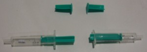
1) The first part of the procedure deals with preparing the syringes. This system is very close to the one presented in [1]. Cut the plungers of 2 syringes, and insert a magnet in one (Fig 1).
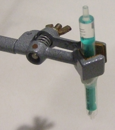
2) Bind them together with the metal wire (Fig 2).
3) Fill the syringe that does not contain the magnet with water and hold it vertical (Fig 3).
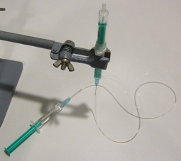
4) Insert the needles in the tubing, fill a third syringe with water, place the needle in position, flush the tubing with water and connect the syringe with the free needle (Fig 4). Make sure no air bubbles are present in the water phase: they will increase the response time of the system to flow rate modifications.
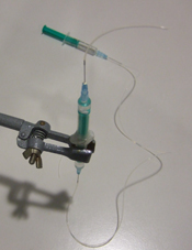
5) Invert the syringe to have the magnet in the upper part and fill this part with the liquid containing the cells, beads or particles (Fig 5) and connect a short needle with tubing (Fig 6).
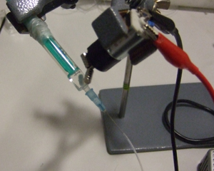
6) Rotate the syringe and mount the motor with the magnets. Turn on the power supply (Fig 7). The speed of the motor is simply controlled by the voltage to guarantee gentle agitation of cells.
7) The system is now ready to be connected to a chip on one hand and to a syringe pump on the other (see video below). More sophisticated systems can probably be adapted to allow a temperature control of the syringe.
References
[1] R. Cooper and L. Lee, Preventing suspension settling during injection, Chips & Tips (Lab on a Chip), 21 August 2007.
[2] L. Capretto, S. Mazzitelli and C. Nastruzzi, An easy temperature control system for syringe pumps, Chips & Tips (Lab on a Chip), 22 April 2008.


